Changing Component Colors in SOLIDWORKS Drawings
Table of Contents
The devil is in the detailing, and getting all our intentions from our 3D model in our 2D drawings can be difficult. Oftentimes, we have a need to highlight one particular component or subassembly in its larger context, and managing this can be challenging.
This need can be further confounded where both structural and mechanical elements need to be defined, or when our internal procedures or data management dictate how drawing files are made from parts, subassemblies, and assemblies.
Layers
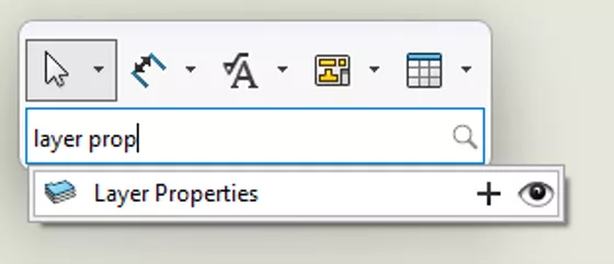
Both methods we’ll be exploring revolve around using SOLIDWORKS Drawings layers in different ways. Checking your layer properties is easy. Open or create a Drawing and press the “S” key and search for Layer Properties.
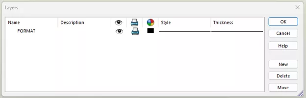
The Layers dialogue box will show you all the layers and associated colors available in that Drawing. As you can see in my example, I have only a single layer available with black lines.
By clicking the New button, I can add layers to my Drawing.
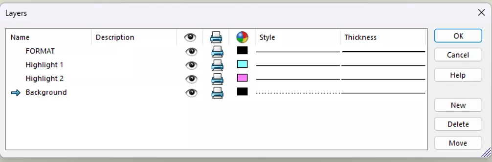
Here you can see that I have increased the thickness of my default FORMAT layer, but added multiple highlights and a dashed line style for components I want to de-emphasize.
For more information on SOLIDWORKS Drawings and layers, the video by my colleague Shivani Patel is a great introduction towards the bottom of this blog: How to Use Layers in SOLIDWORKS Drawings
Method 1: Changing Colors Across All Views
Changing the layer a component is on is by far the simplest. Right-click a component and select Change Layer to choose a layer to place the component on. Optionally, left-click a component and choose the layer from the Layers Toolbar if that is activated.
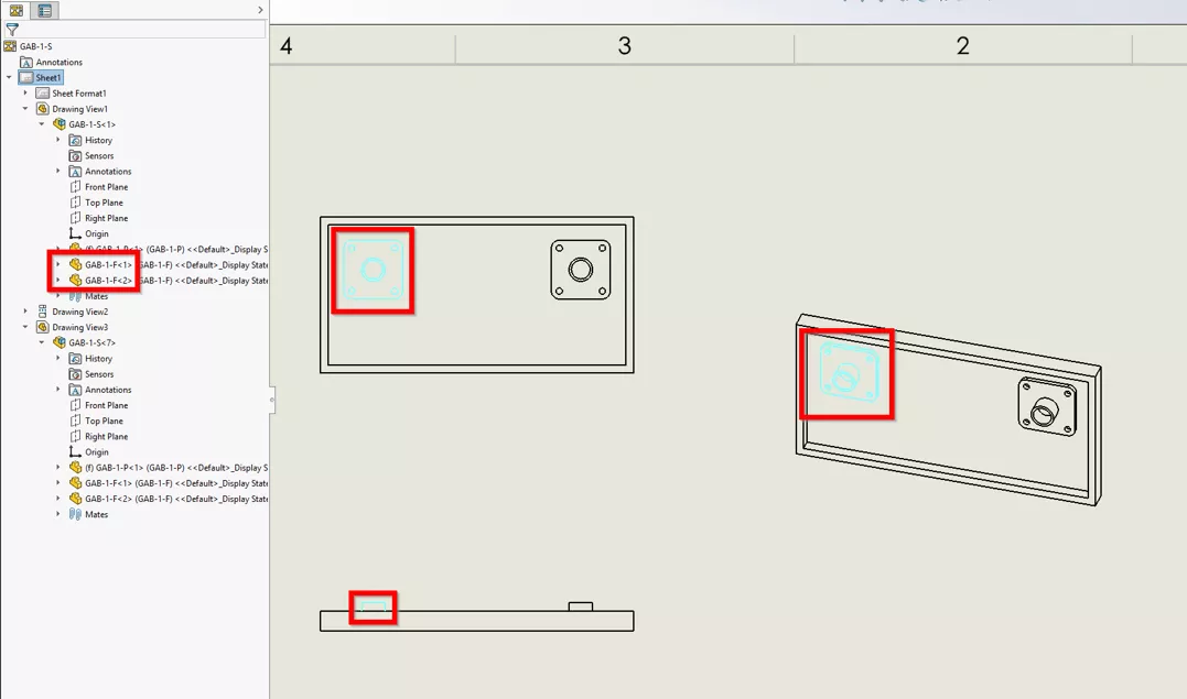
Note that the same component is changed in every view in every sheet of the drawing, but not every instance of the same component. We can see in our FeatureManager Design Tree that there are two instances of the same GAB-1-F component in the same configuration, but only the selected instance is changed across all views.
The greatest strength of this method is, however, its greatest weakness: every single view in every single sheet of the same Drawing is changed.
Method 2: Changing Colors Individually
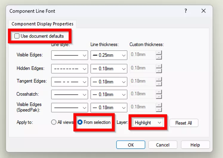
For a more targeted approach, right-click a component and select Component Line Font in the Drawing.
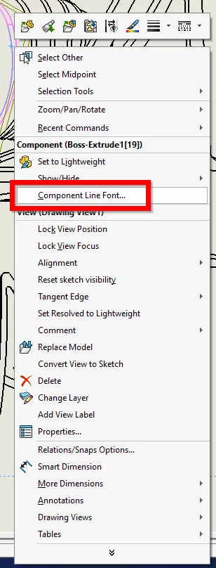
Clear Use document defaults, set the Apply to setting as From Selection, and then choose the layer.
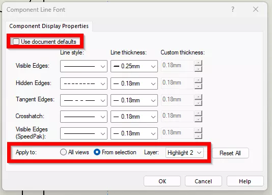
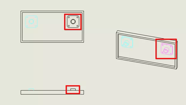
This will change only the selected component in that view.
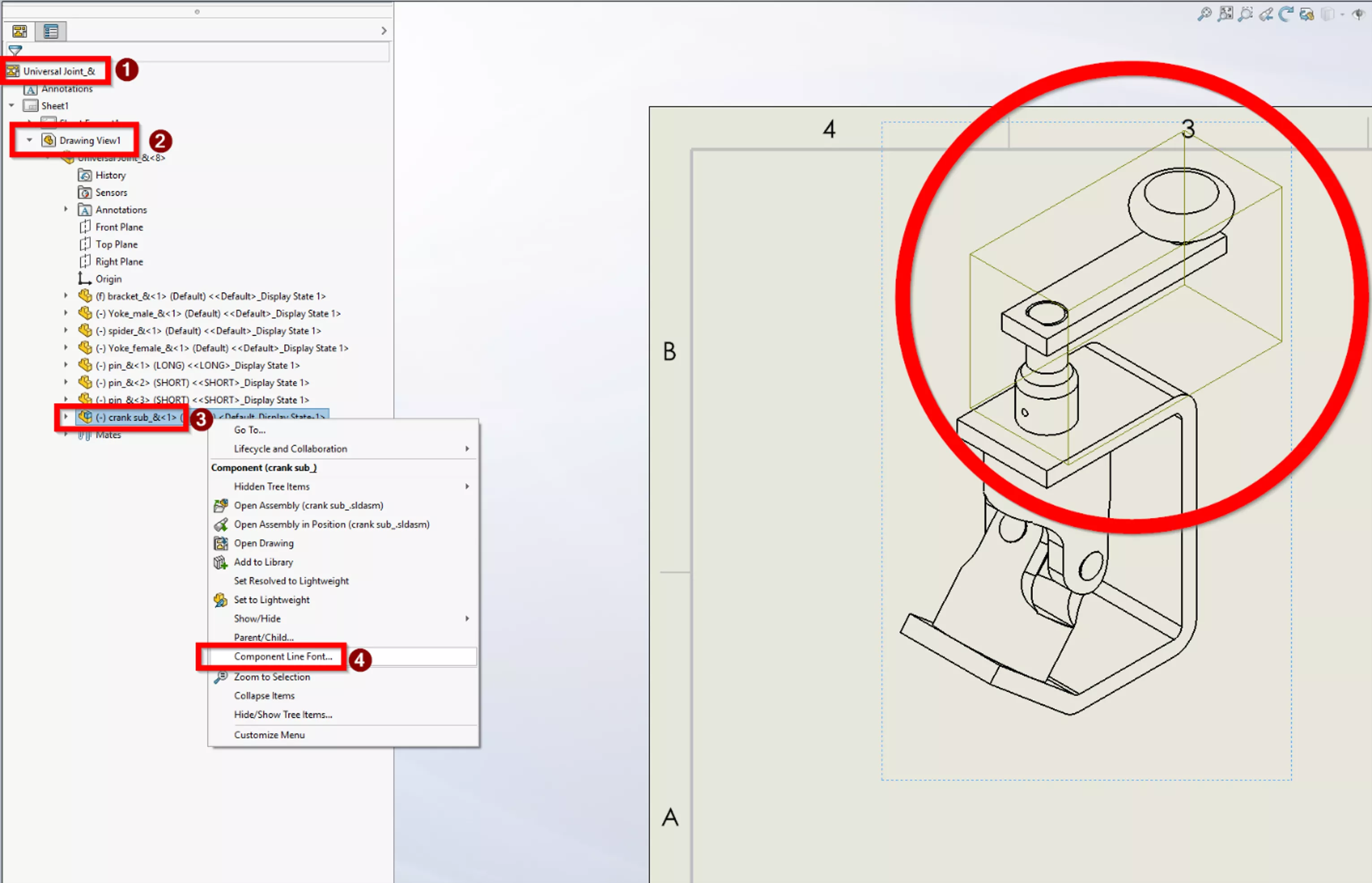
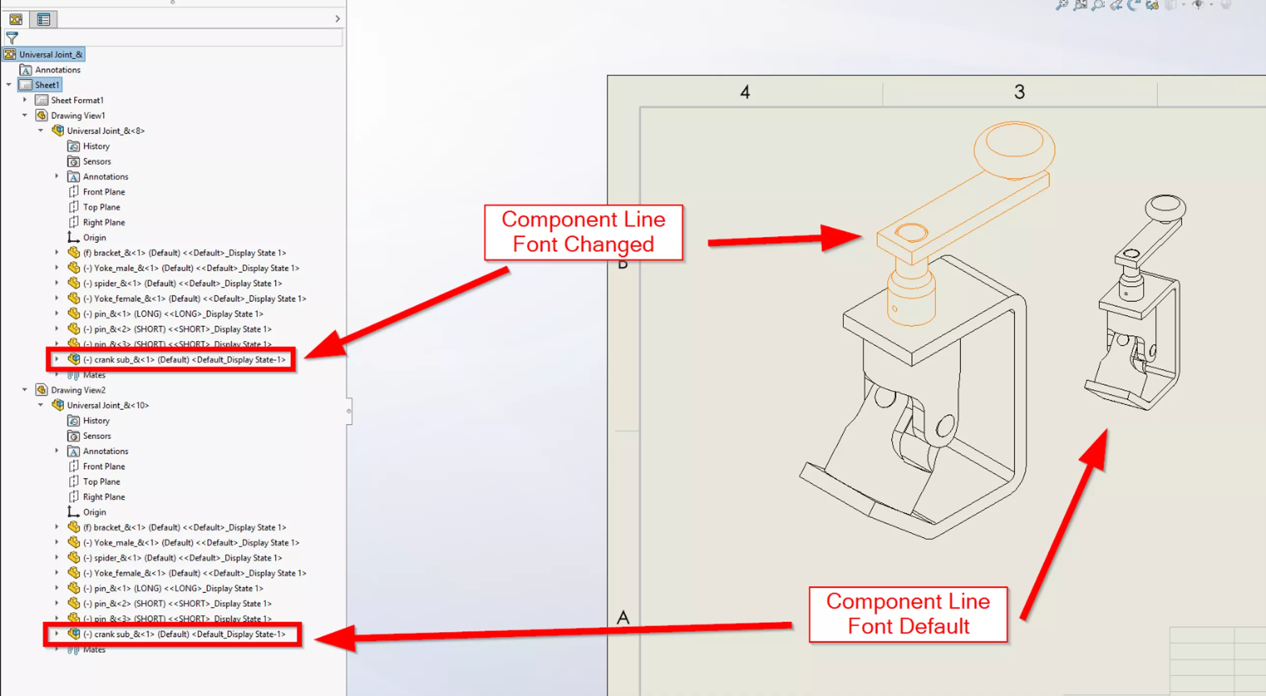
If one needs to change an entire subassembly instead of one part, expanding the FeatureManager Design Tree will reveal the full assembly structure within each view on each sheet. Right-clicking the entire subassembly will change that entire subassembly in the desired view.
Top Tips
Search the FeatureManager
One of my favourite tools in SOLIDWORKS is the ability to search the FeatureManager Design Tree in Parts, Assemblies, and Drawings by simply clicking next to the filter icon and typing.
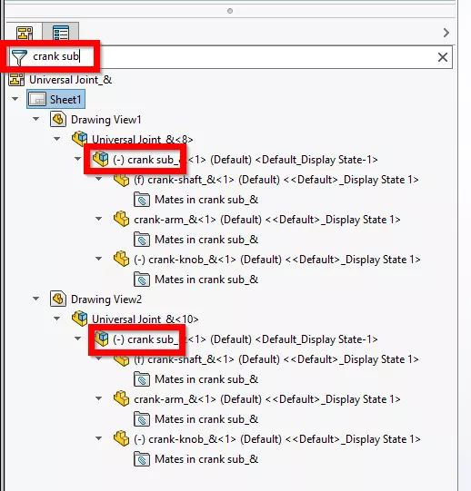
From here, we can rapidly change the component line font on every view across any number of sheets. If the same Drawing document contains both Structural and Mechanical drawing sheets, we can easily highlight the correct views on the correct sheets by filtering the entire Drawing from the FeatureManager.
Automation with Drawings Templates
Creating Drawings templates with all the information we need is a critical procedure for any company using SOLIDWORKS, and we can have all of our layers automatically created with our templates. From there, we just right-click away!
For more information on customizing your SOLIDWORKS Drawings templates, take a look at these resources:
- SOLIDWORKS Drawing Templates
- Applying a New SOLIDWORKS Drawing Sheet Format to Existing & Future Drawings
With the correct use of the “Per Standard” Layer control and these customizations, you can get a lot of work out of each sheet.
Automating with Macros
After your document templates are customized, you can also record a quick macro to rapidly put parts on the desired layers to really speed up detailing!
One could create buttons to, for instance, put an entire view in the background while having custom buttons for mechanical highlights and another for structural highlights.
For more information about recording a custom macro, take a look at this blog post: Record a Basic SOLIDWORKS Macro
Conclusion
SOLIDWORKS Drawings are frequently the final destination for our Part and Assembly models. Getting our components appropriately defined and described is a whole field of challenges separate from designing them, and I hope this article helps expose tools, workflows, and automation to get your products done faster.
Want to learn more? Check out more tutorials and tips below, or check out the GoEngineer Community, where you can create forum posts, enter design contests, and answer questions from other SOLIDWORKS users.
SOLIDWORKS CAD Cheat Sheet
SHORTCUTS ⋅ MOUSE GESTURES ⋅ HOT KEYS
Our SOLIDWORKS CAD Cheat Sheet, featuring over 90 tips and tricks, will help speed up your process.

Related Articles
Modeling Conveyor Belts with Cleats in SOLIDWORKS
Intro to SOLIDWORKS Sketch Blocks
AI in SOLIDWORKS: What It Is (and What It Isn’t)
Adding O-Ring Grooves to a SOLIDWORKS Part

About Mike Britton
Mike Britton is a SOLIDWORKS Application Engineer based out of Ontario, Canada. In addition to his work with GoEngineer, Mike is a competitor on Discovery Channel's BattleBots and volunteers with his childhood summer camp & local makerspaces.
Get our wide array of technical resources delivered right to your inbox.
Unsubscribe at any time.