Adding User Defined Turning Tools to CAMWorks
In SOLIDWORKS CAM and CAMWorks, the Technology Database (TechDB) allows for adding user defined tools. The process for adding Turning tools is a little different than that of adding Mill tools.
Turning tools can be imported as an assembly, the Turning Insert, and the Turning Tool Holder. You can add just the Turning Insert to your library, but since many manufacturers can provide a 3D model of the tool and insert, we’ll focus on adding a user defined Turning tool from a model of the new tool and insert.
The process involves 3 steps:
- Create a Coordinate System for the insert and holder in the assembly
- Add the User Defined Tool to the TechDB
- Select the User Defined Tool for the Operation
Create the Coordinate System for the User Defined Tool
We’ll start by opening the 3D model of the tool we want to add to the TechDB. In this case, the tool came from the tool manufacturer as a .STP file, so it will need to be imported.
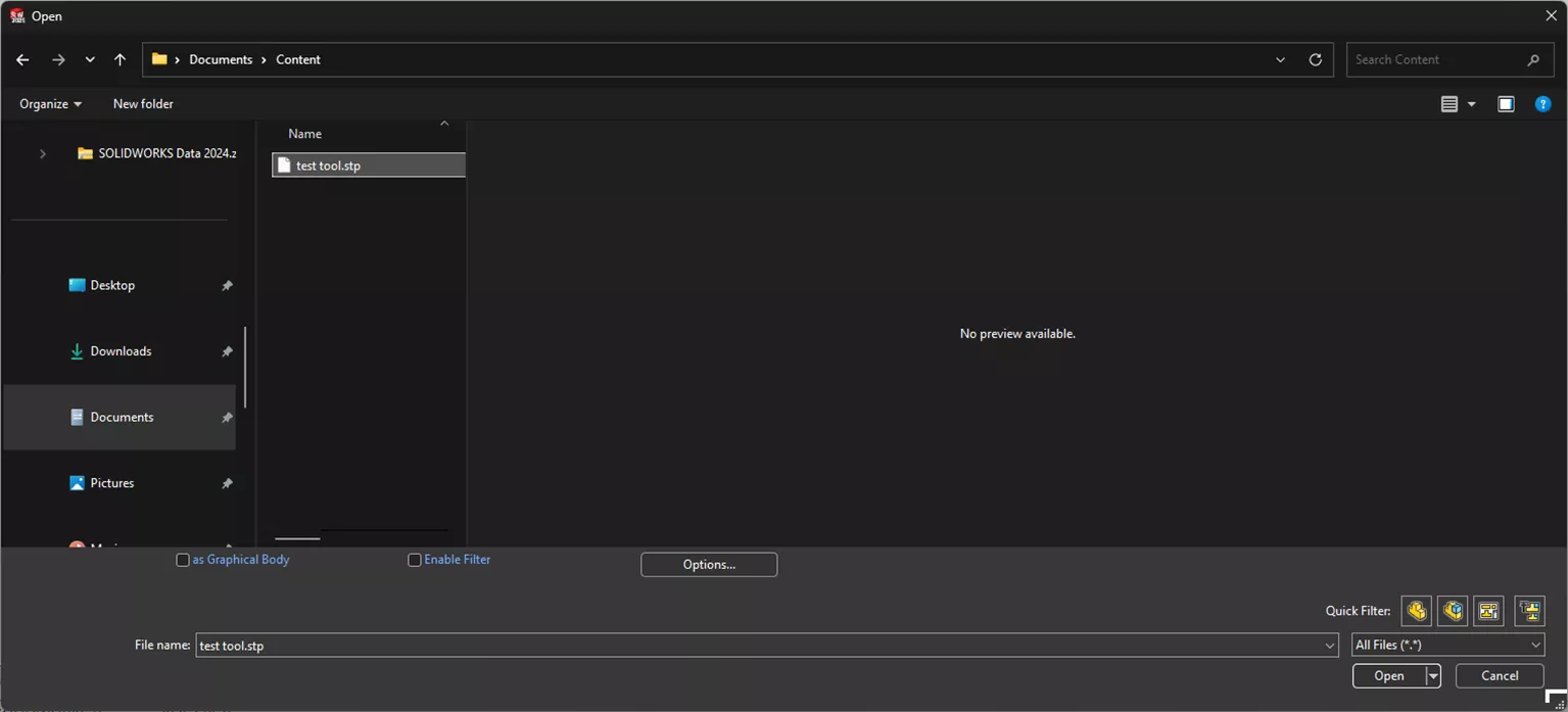
Once the .STP is imported, there should be two parts in the assembly CUT (insert) and NOCUT (holder).
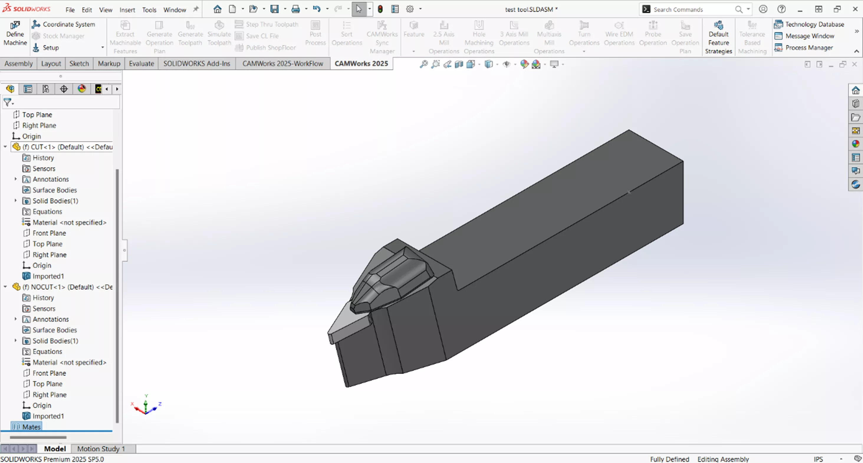
We now need to create a coordinate system that will allow the tool to be properly oriented for our machine. To do so, start by creating a sketch on the face of the insert and draw lines colinear to the edges of the insert and extended to where they would intersect. Add a vertical construction line from that point across the face of the insert. Where the line ends is not important (shown below). Close the sketch.
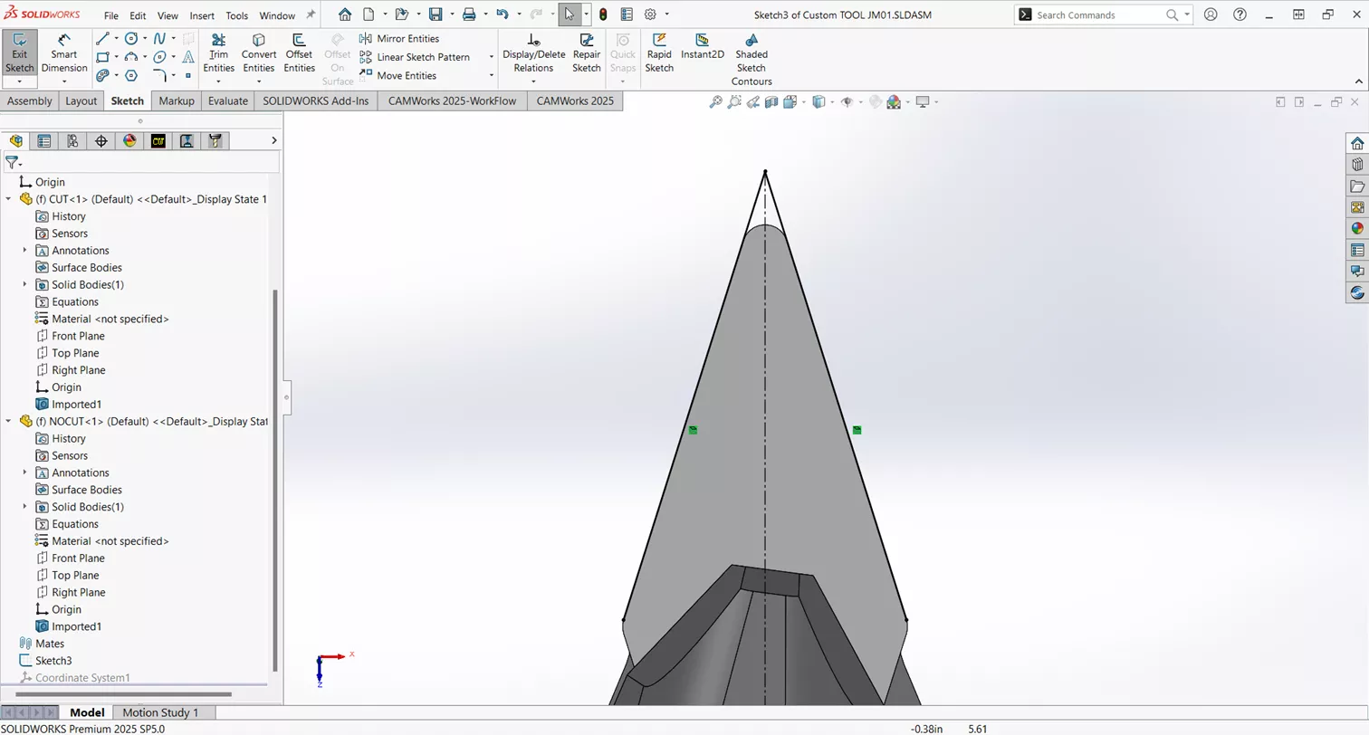
Now, create a Coordinate System by selecting the Assembly tab in the Control Manager, Reference Geometry > Coordinate System.
We need to create a Coordinate System that will correctly orient the tool for our machine. In this case, we want the tool orientation to be down left.
To accomplish this, we’ll create the Coordinate System at the virtual sharp of the insert we created in our sketch, with the X-axis along the construction line of our sketch, and the Y-axis normal to the body of the tool holder.
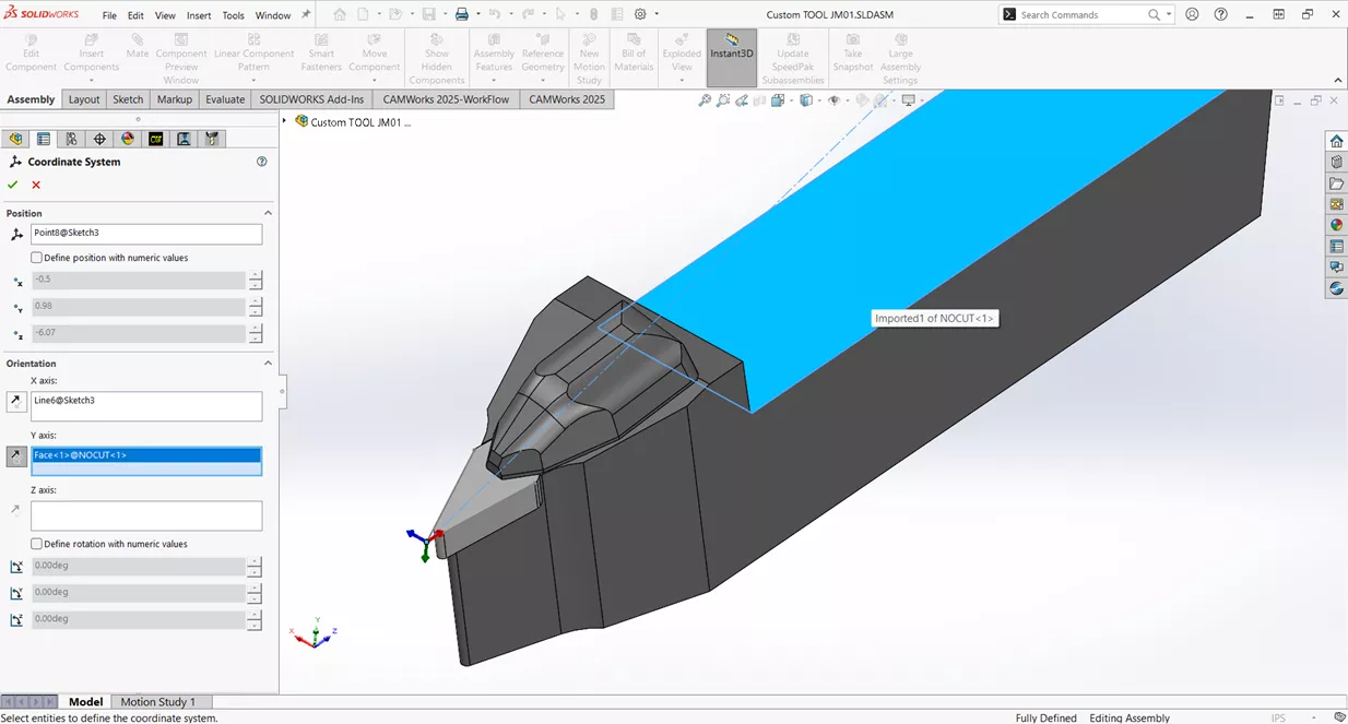
Hit the green check to save the assembly to the desired location.
Add a User Defined Tool to the TechDB
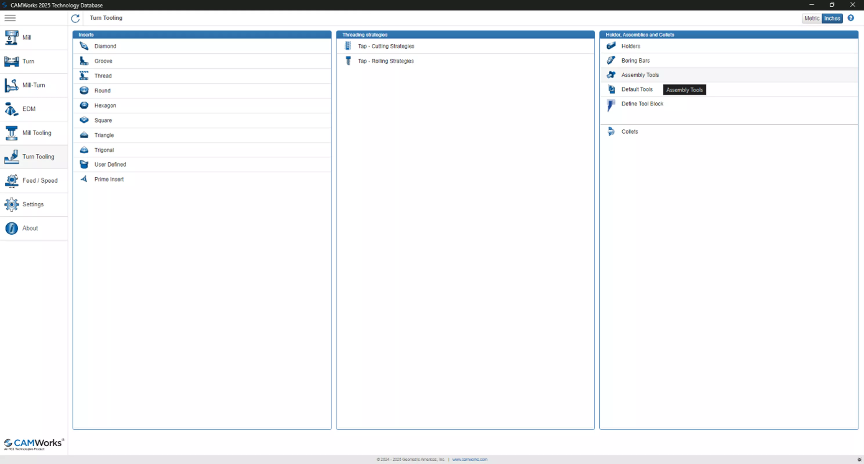
Now, we’ll need to add this tool to the TechDB. Open the TechDB and select the Turn Tooling tab from the left panel, then Inserts > User Defined.
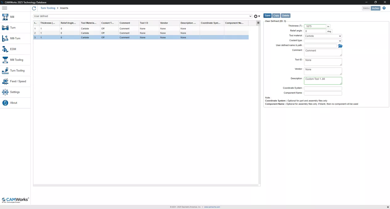
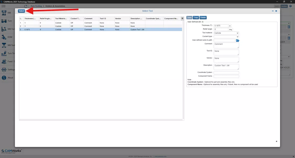
There is no “Add” option, so we’ll need to copy an existing insert, enter the appropriate insert thickness (.1875 in this case), and a description. Since we have the full assembly of the insert and tool, we do not need to link the insert part file here. Click save and return to the Turn Tooling tab, then select Holder > Assembly Tools.
As with the insert, we’ll need to copy an existing tool. Change the Insert Type to User Defined, and select the insert just created.
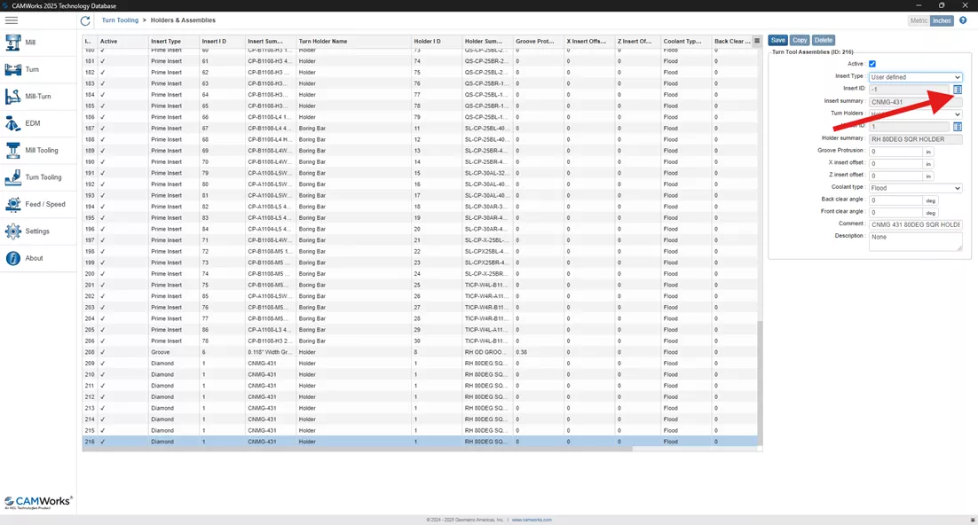
Add a Comment and Description for your tool, click Save, and close the TechDB.
Select the User Defined Tool for the Operation
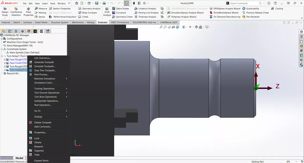
In SOLIDWORKS, select the toolpath that will use your user defined tool. Right-click on it and select Edit Definition.
In the Operation Parameters, select the Tool > Tool Crib.
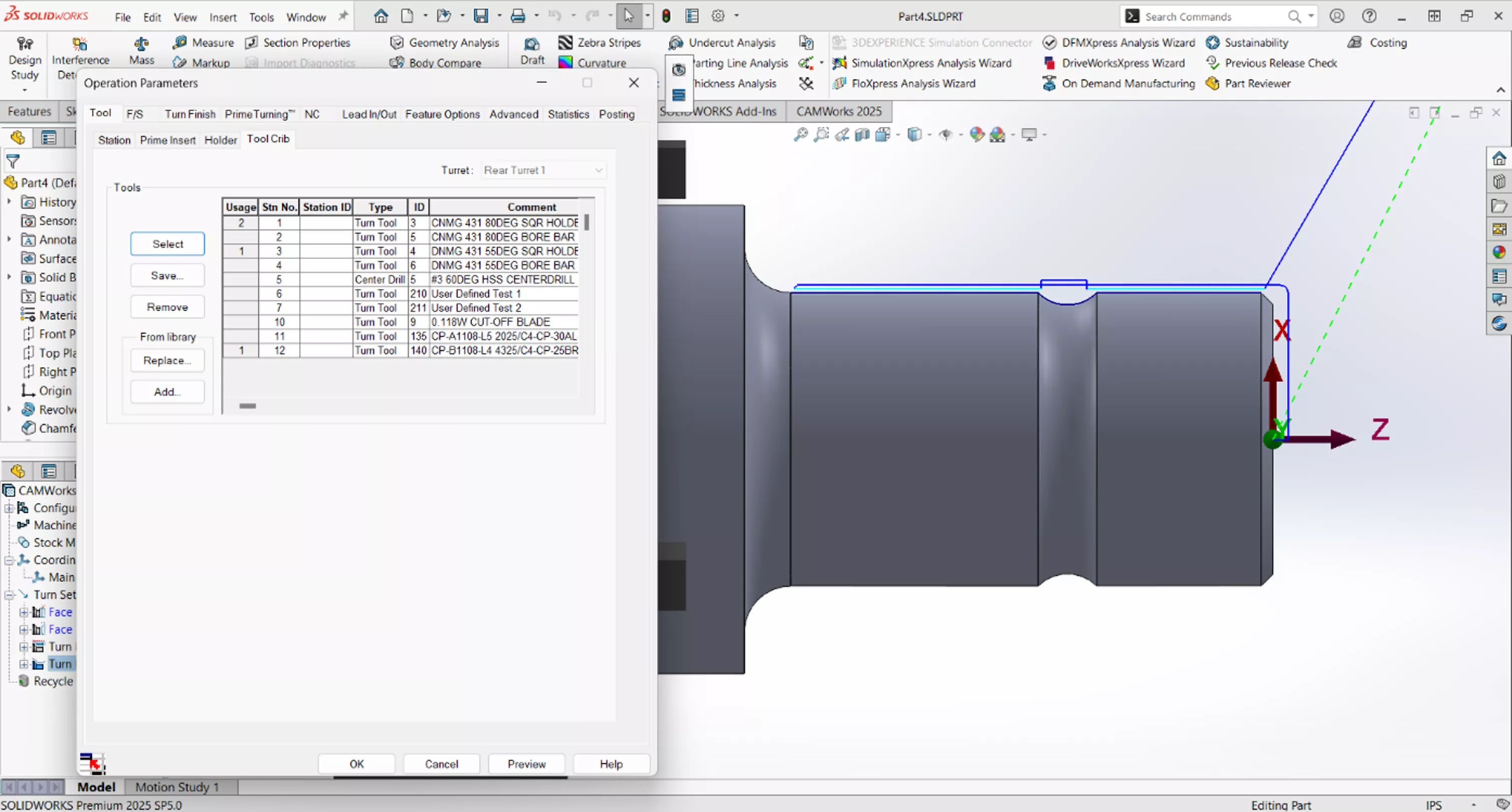
Click From Library > Add.
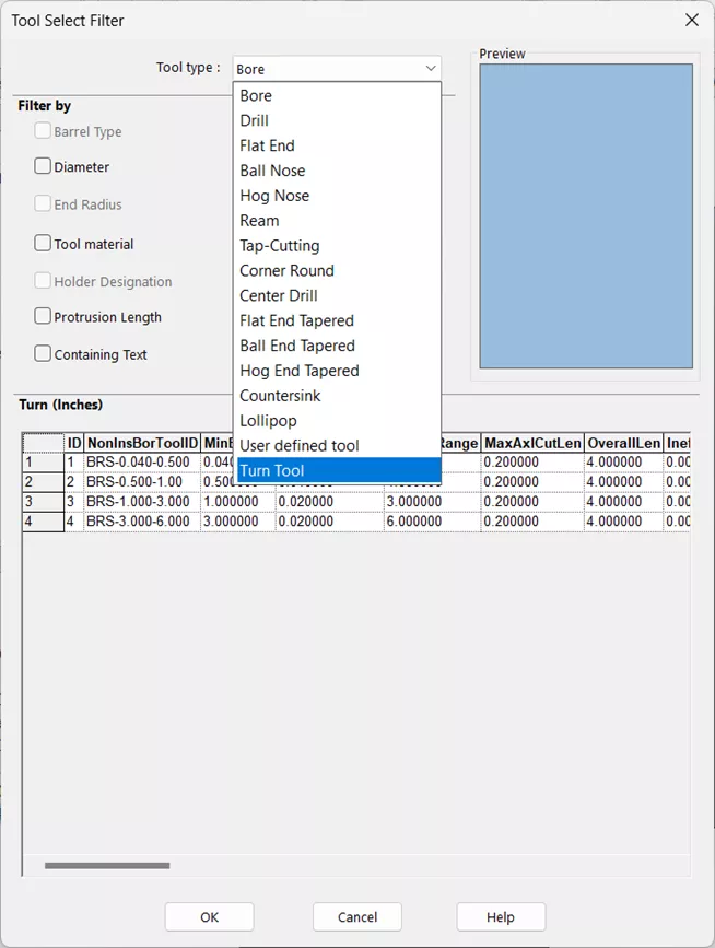
Change the Tool Type to Turn Tool.
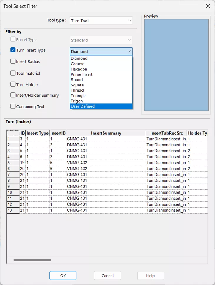
Then change the Turn Insert Type to User Defined.
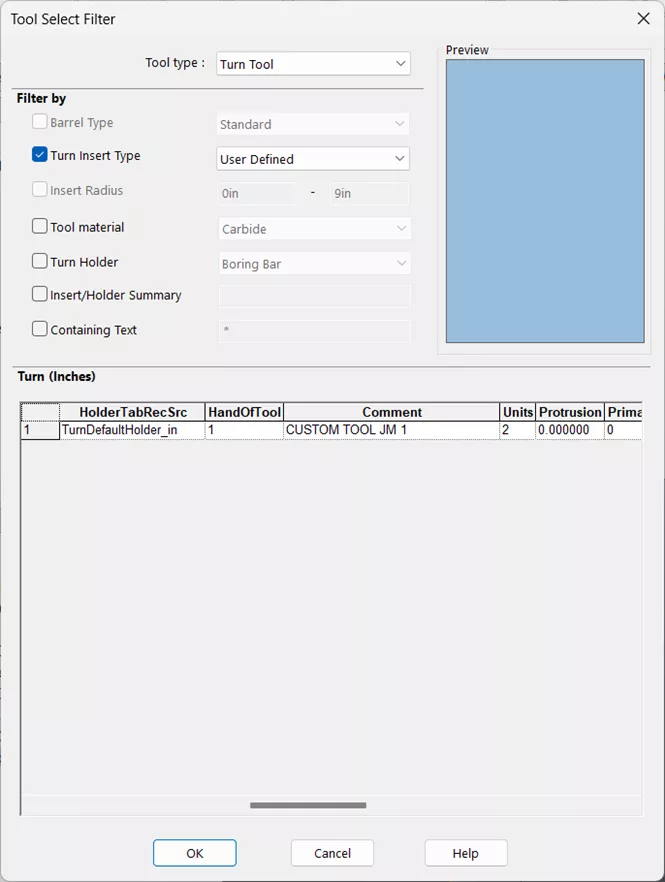
The user defined tool should be available. Select it and click OK.
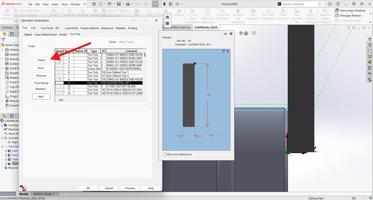
In the Tool Crib tab, select the new tool.
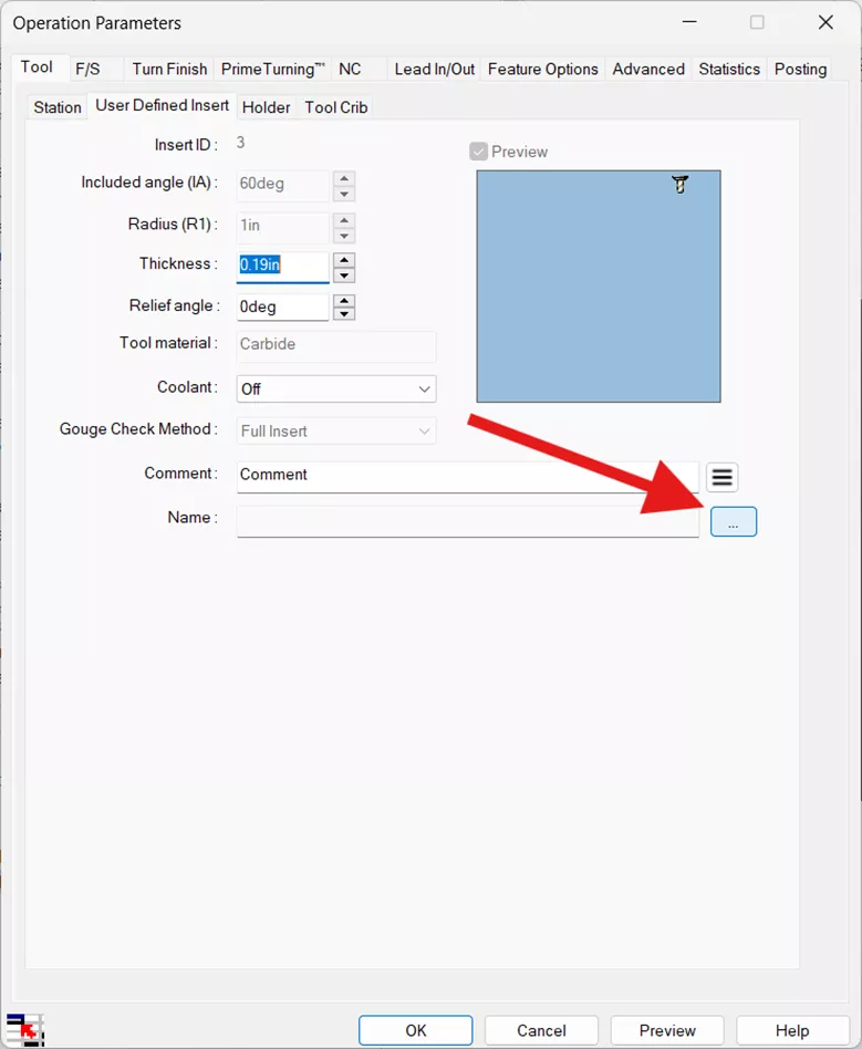
Now we’ll link the tool with the assembly we created earlier. Navigate to the User Defined Insert sub-tab of the Tool tab and click on the ellipsis.
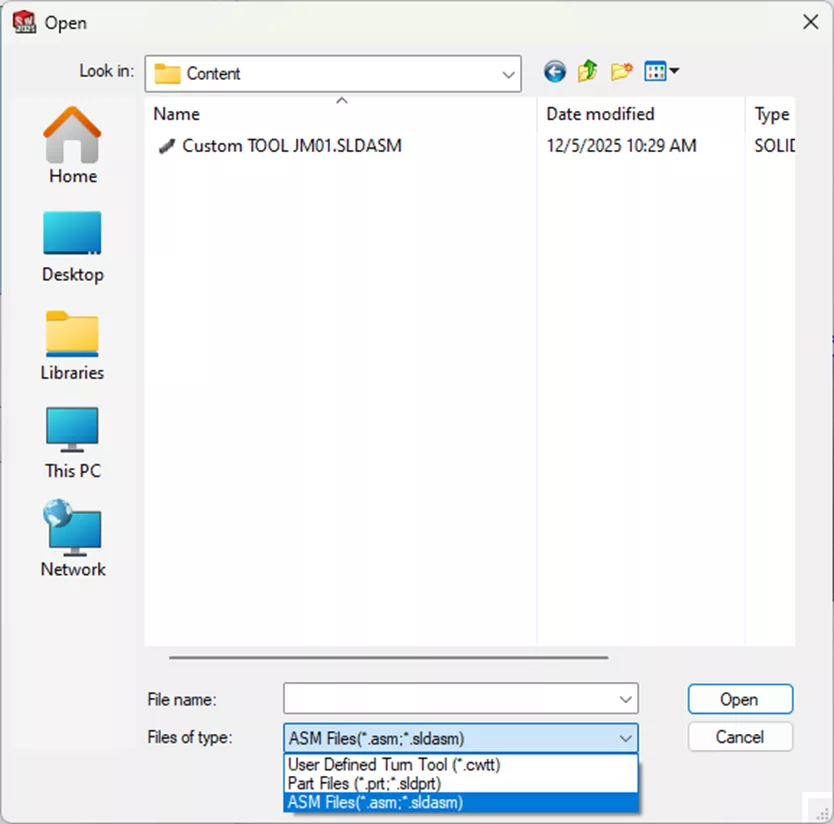
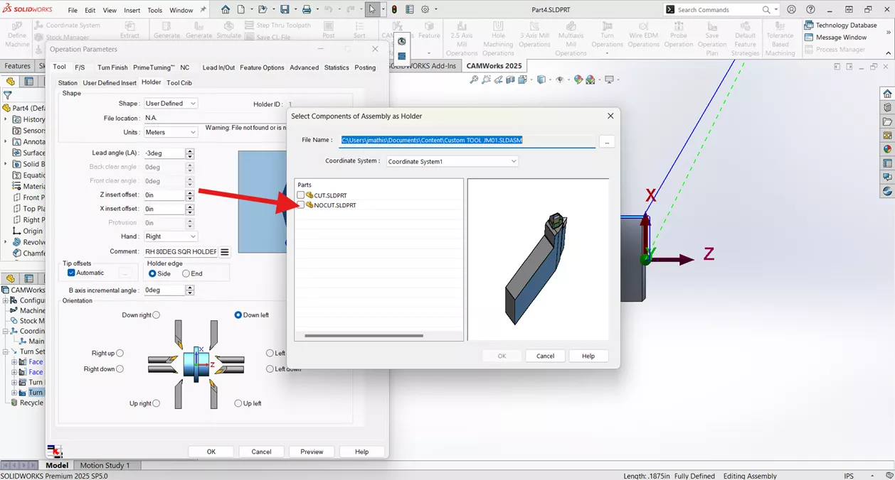
Navigate to the folder your tool assembly is saved in, change the file type to view SOLIDWORKS files, and select the tool assembly.
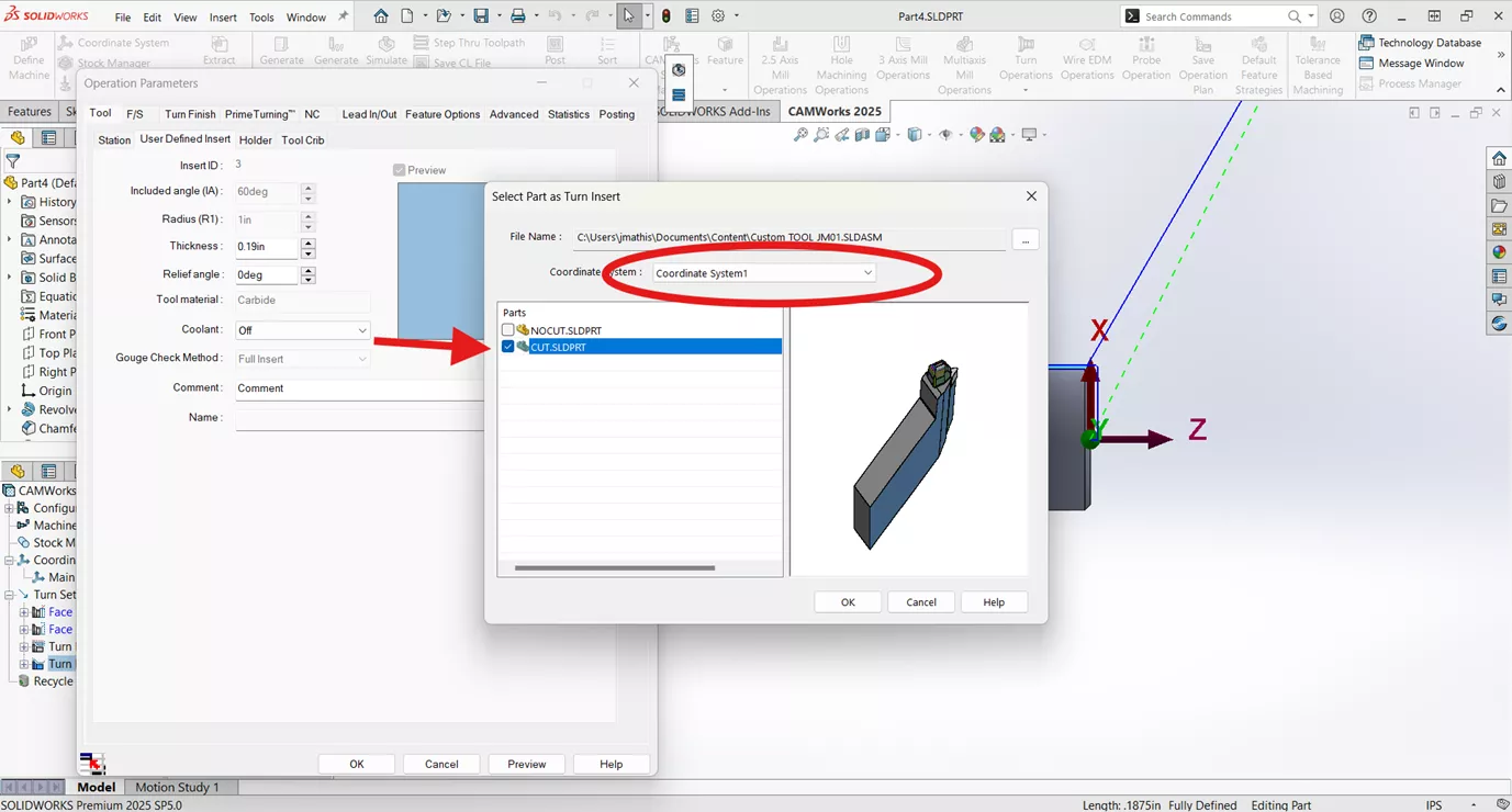
Since we are setting up the insert, select the CUT component and ensure that the coordinate system that was created is selected.
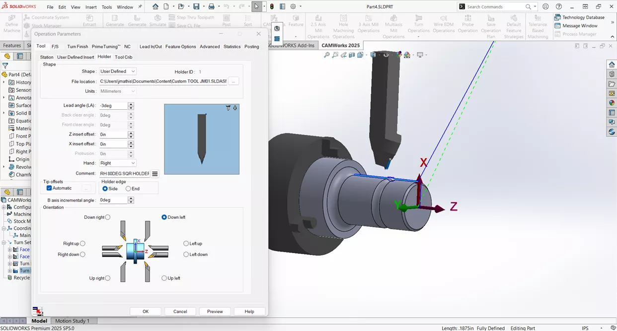
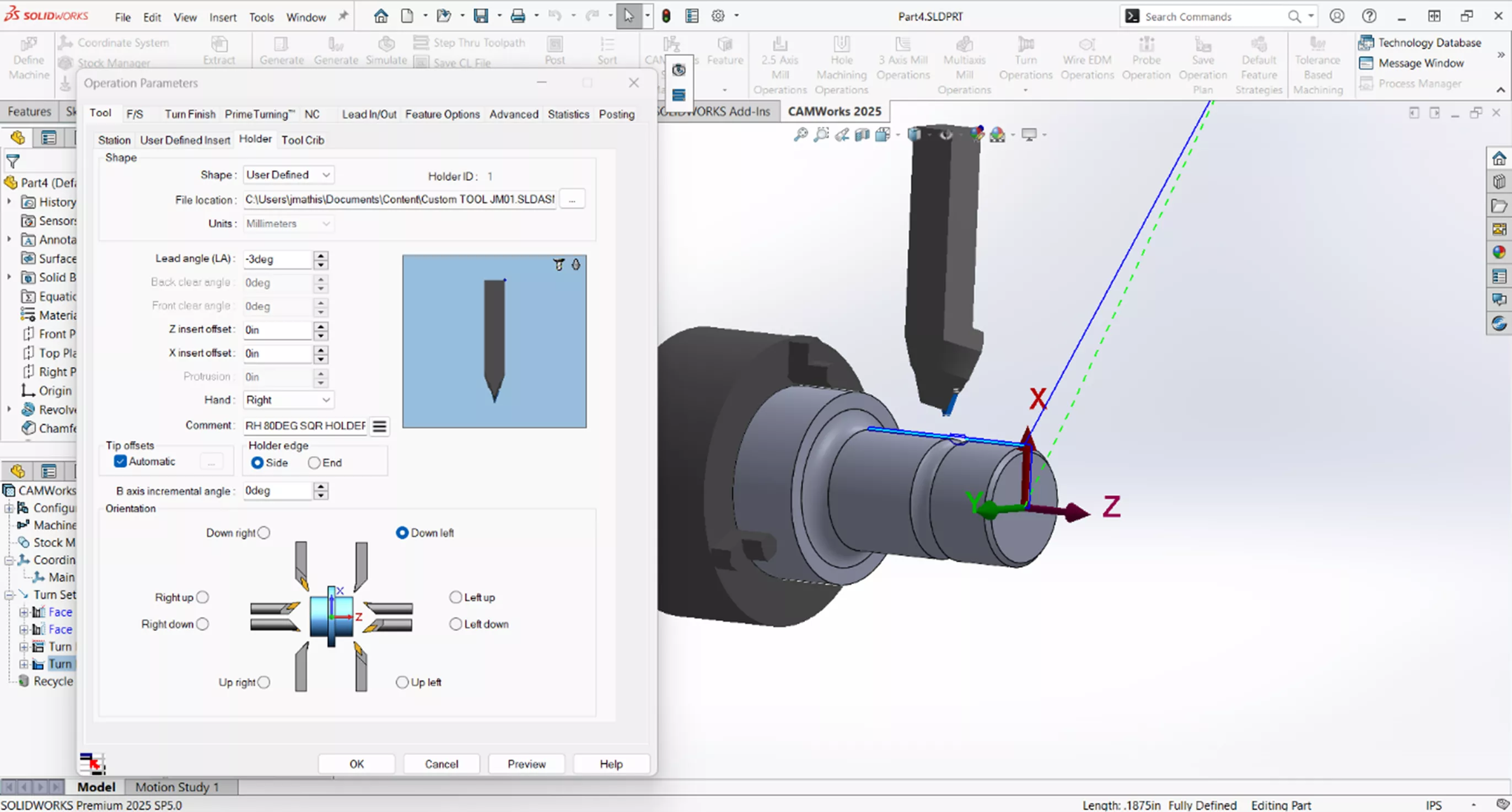
Next, click on the Holder sub-tab of the Tool tab. Change the Shape to User Defined.
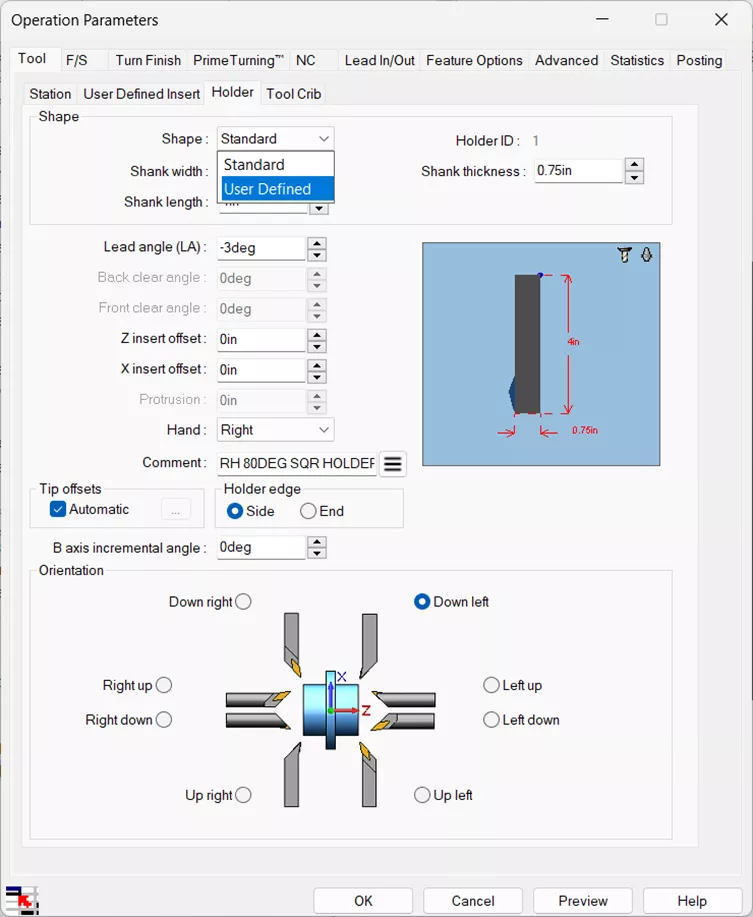
Click on the ellipsis to add the file path for the tool holder. Navigate to the same location as the insert and change the File Type to see the SOLIDWORKS assembly. Ensure that the correct Coordinate System is selected, and this time, we’ll choose the NOCUT, since it's just the holder we want.
The insert and holder should now display correctly in the preview and the model.
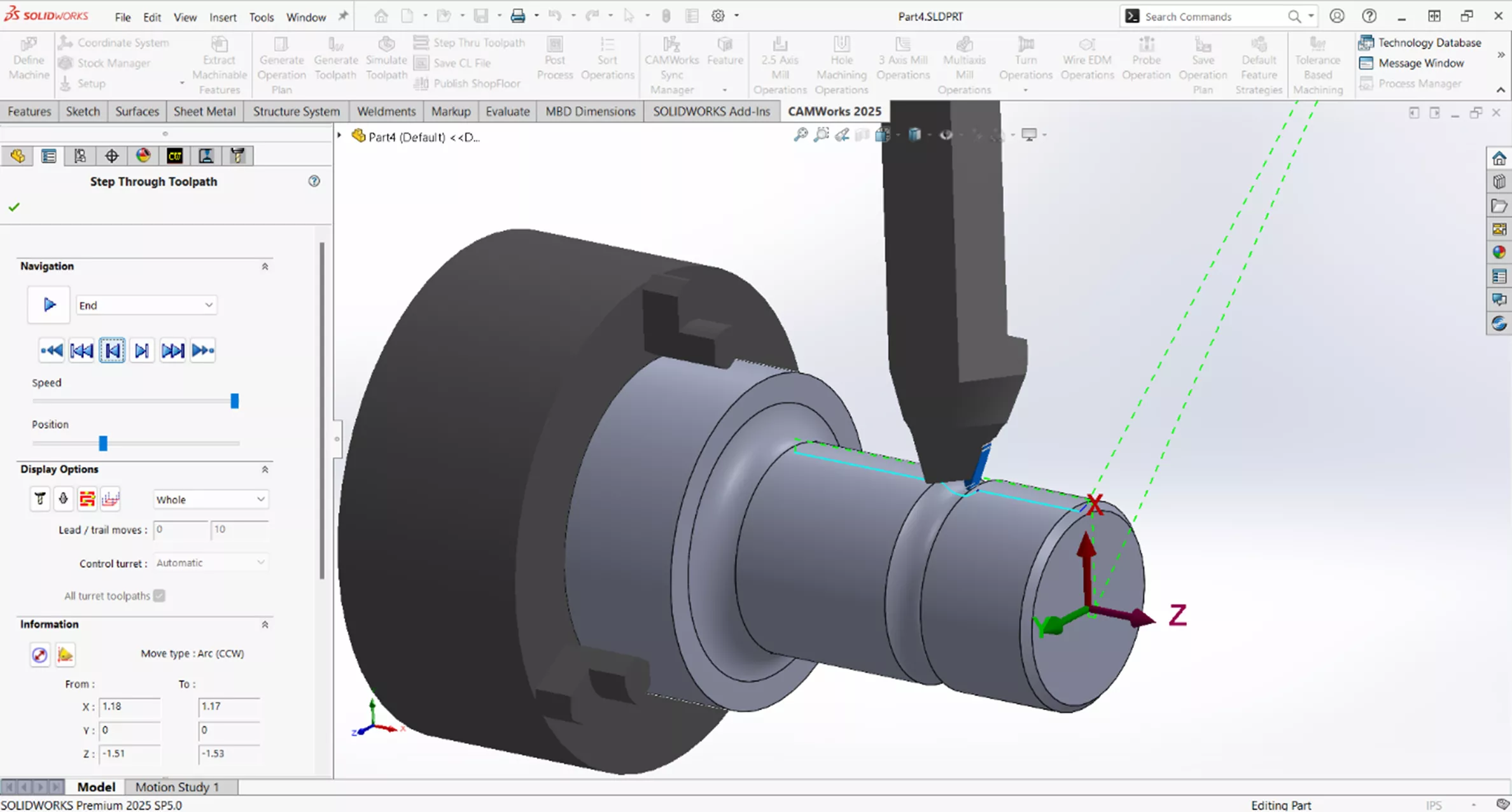
Finally, you can step through the simulation to verify that the tool is oriented properly.
Successfully adding user defined Turning tools to the Tech DB in SOLIDWORKS CAM and CAMWorks enhances machining capabilities by allowing for precise customization. By following the outlined steps, users can ensure optimal tool orientation and functionality for their specific machining operations.
Want to learn more? Check out more tips and tricks listed below. Additionally, check out the GoEngineer Community, where you can create forum posts, enter design contests, and answer questions from other SOLIDWORKS and CAMWorks users.
Related Articles
CAMWorks Broaching - Turn Setup & Mill Setup
When to Use an Open Pocket Without Sketches in CAMWorks
What's New in CAM 2026: SOLIDWORKS, CAMWorks, & More

About Justin Mathis
Justin Mathis is a Mechanical Engineer based out of Columbus, Ohio. He holds a CSWE certification and has 15+ years experience in machining and manufacturing. Justin has been part of the GoEngineer family since August 2024 as a Support Engineer. He likes to spend his off time volunteering in his community, homebrewing, and traveling.
Get our wide array of technical resources delivered right to your inbox.
Unsubscribe at any time.