When to Use an Open Pocket Without Sketches in CAMWorks
When working with features, it is important to keep in mind how CAMWorks operates. The Automatic Feature Recognition (AFR) is mostly looking at volumes of material that are being eliminated. It does so by looking at the edges and faces and how they relate to each other. The kind of feature determines how the tool will behave during cutting. For example, if it sees a volume surrounded by only a circular wall, CAMWorks will call it a hole or a circular pocket, depending on the settings. If a volume has walls all around, it is a pocket. If some walls are missing, it is a slot, with the missing walls called Open Air Edges. The volumes in question are called "slots" by the system. This blog will cover using a pocket versus an open pocket without sketches, and when to use which.
Pocket vs Slot Using Extract Machinable Features
A pocket feature is a volume that must be removed, but the tool is not allowed to go beyond the edges. In other words, there are walls all around.
You can contrast pockets with slots. A slot feature is a volume that needs to be removed, but with at least one side open. This requires the tool to go beyond those edges, thus negating the need, in most cases, for sketches.
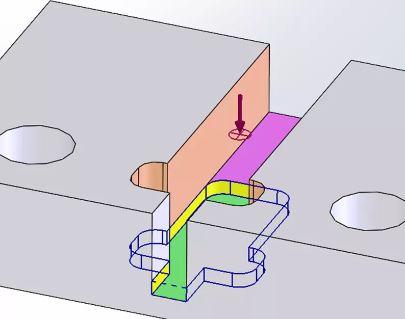
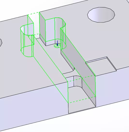
In the part pictured below, the center channel can be processed by looking at two volumes, whose floors are purple and green faces, and go all the way up to the top of the part.
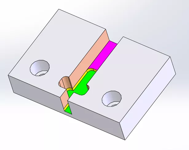
It can also be processed as two separate volumes: one from the top surface to the purple floor (with salmon-colored walls), and another for the next step (green floor with yellow walls).
One of the option settings in SOLIDWORKS CAM or CAMWorks is to recognize features by depth.
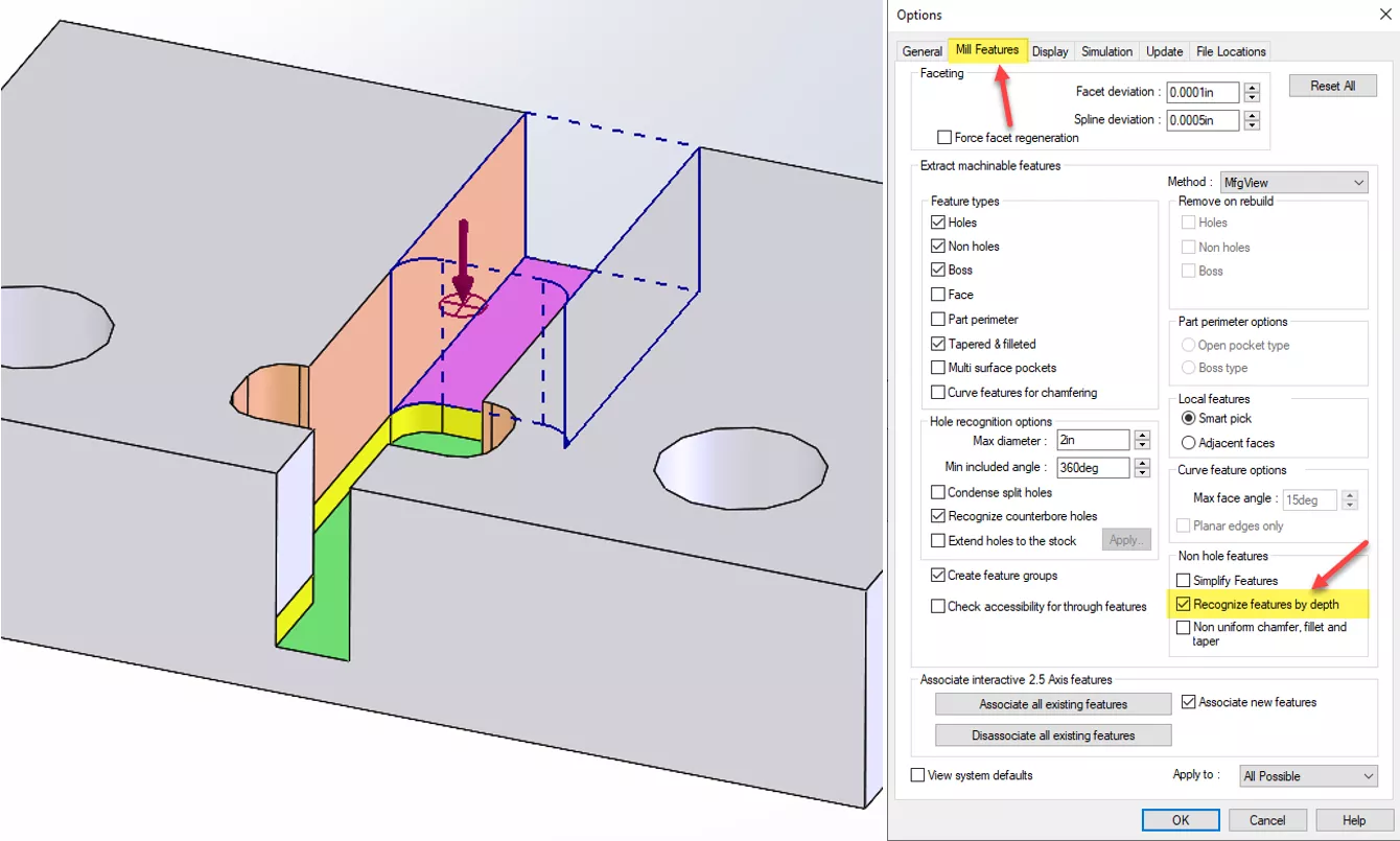
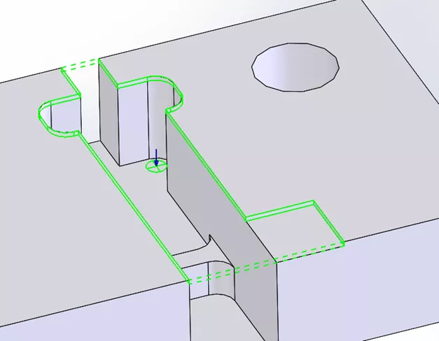
When this setting is used, you end up with two distinct features. Both are called slots because some walls are missing.
Imagine that the part is like a bucket; you start empty and add water to make the level rise. As every floor face is covered (the green first, then the purple), it extends the volume defined by that face by following the vertical edges and removing material all the way up.
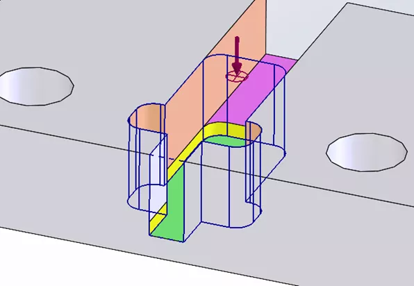
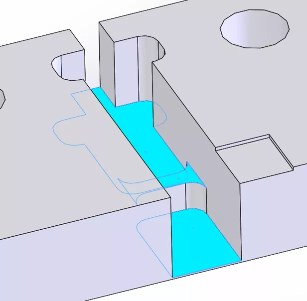
If you set the options to not recognize the feature by depth, the result is something like this:
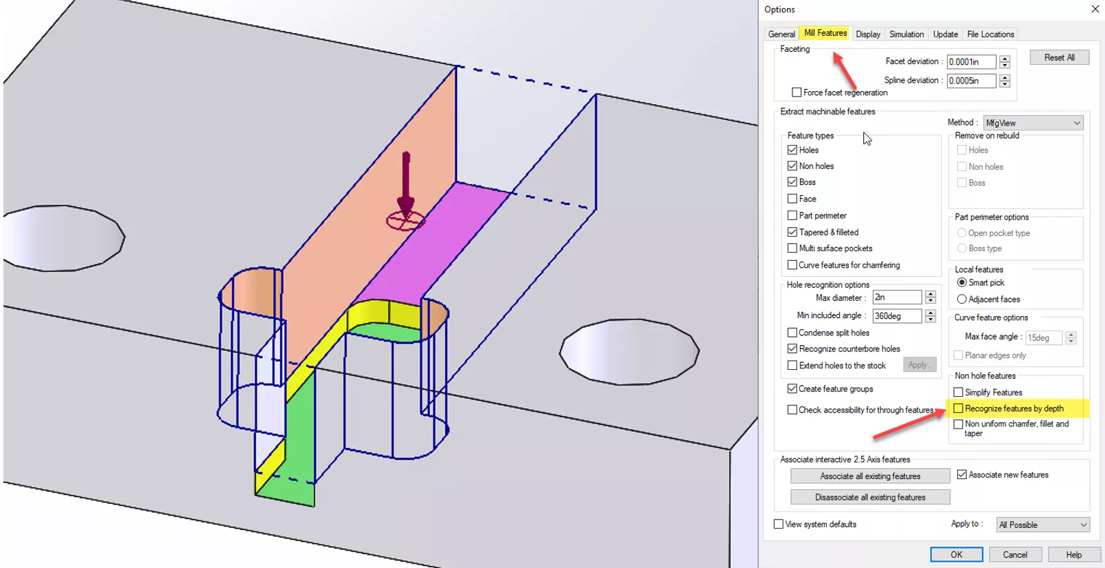
Following the previous analogy, this time the bucket starts full of water. As the level drops, it follows the vertical wall down until it runs into a floor (the purple first, then the green). This results in two slots, but they’re different than the prior method.
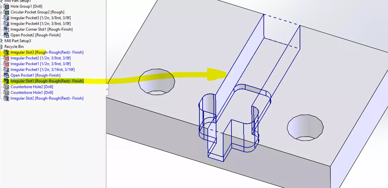
If the system finds a feature and it is deleted but still in the recycle bin, it indicates that the software should ignore it. This is what happened with the original extract features:
When You Need a Sketch
The only time you need a sketch is when the tool pushes past the edge (into open air), a different distance for each slot segment. The operation only allows you to apply a fixed amount to all edges (limit is 150% of the tool):

For a pocket or slot, you can define it by selecting edges, faces, and vertical walls. If you pick two floors at differing heights, the system will separate them into two distinct features. It will act as if you checked the recognize features by depth setting.
When you select vertical walls, CAMWorks can only close one edge. In this sample part, there are two missing edges, making it impossible to make a closed shape. That requires a sketch.
We changed configurations in SOLIDWORKS to the To add Features configuration.
Note: Depending on what is needed, you may need to use the Recognize Local Features tool.
I added to the center channel by extracting machinable features with the setting recognize features by depth unchecked in the options. Notice that it adds an entire feature to the depth of the small square:
For clarity, delete just the found features and keep the Mill Part Setup.
Next, hold CTRL and select the floors:
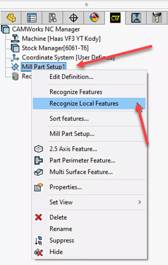
Then, right-click on the Mill Part Setup and select recognize local features.
CAMWorks tries to add the faces and comes up with a deep slot, ignoring the small square.
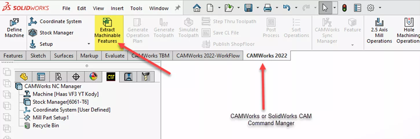
Next, run the Extract Machinable Features under the CAMWorks toolbar.
Finally, pick the faces and use the Recognize Local Features tool.
For more hands-on experience with this, check out some of the examples installed by CAMWorks under these conditions. This will help you develop the mental image of what the AFR is going to find, depending on the setting in the Mill features tab in the SOLIDWORKS CAM or CAMWorks Options.
Related Articles
How to Machine Large Hole Chamfers in CAMWorks
What's New in CAM 2026: SOLIDWORKS, CAMWorks, & More
What Is Feature-Based CAM and Why Is It Important?

About Krystal Petersen
Krystal Petersen is a SOLIDWORKS Technical Support Engineer based out of Auburn Hills, Michigan. Krystal studied Product Engineering at Oakland Community College and has earned her CSWA and CSWP Certifications. She joined the VAR channel in 2015 with DASI (now GoEngineer). Krystal is a huge fan of Star Wars and likes to spend her off time fishing and camping.
Get our wide array of technical resources delivered right to your inbox.
Unsubscribe at any time.