SOLIDWORKS Exterior Miter Flange Tip
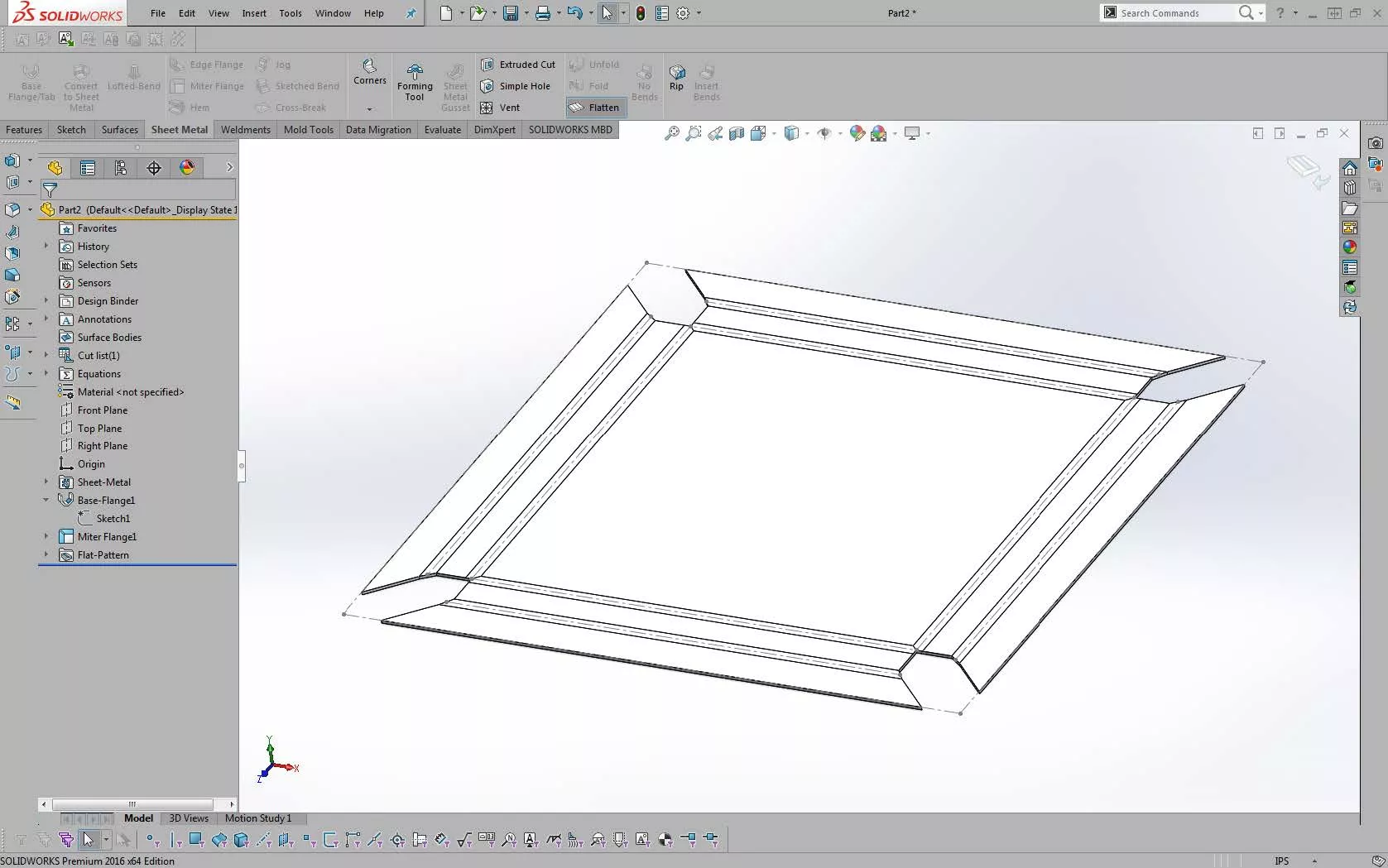
Have you ever come across the problem of having a flange on a sheet metal part in SOLIDWORKS? When an exterior flange is needed to have the ends of the flange mitered, it can be difficult to create that feature. Our goal in this quick tip is to produce something similar to this:
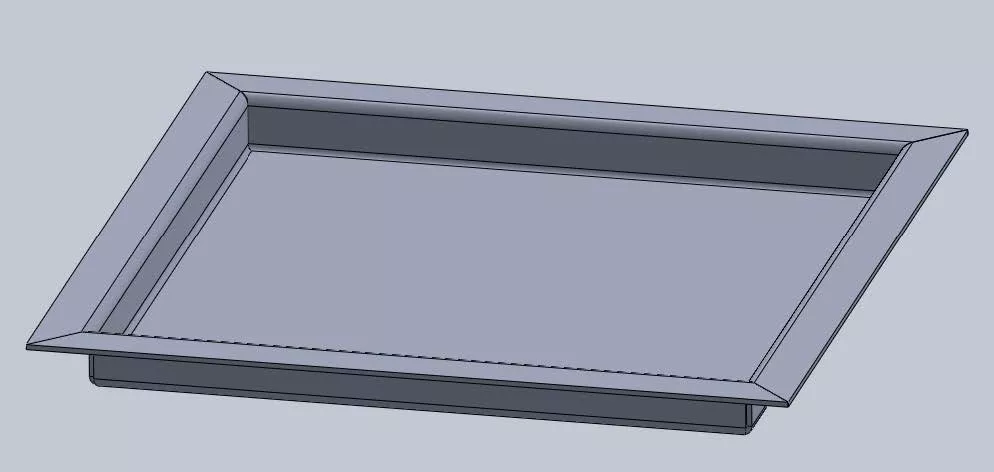
How do we create this?
SOLIDWORKS Exterior Miter Flange
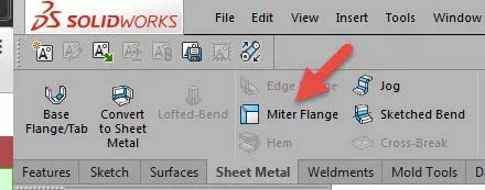
If you look under the Sheet Metal tab in SOLIDWORKS, you will see the icon for Miter Flange.

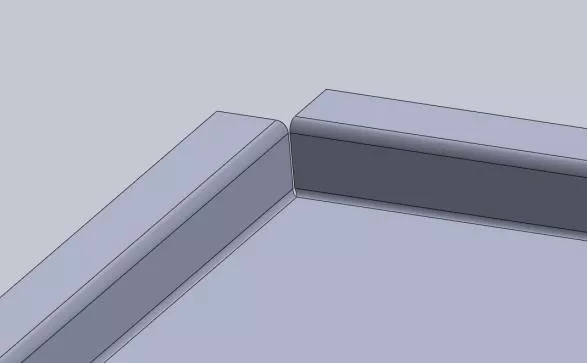
Normally, when we create a standard flange in Sheet Metal using just the Edge Flange option, we get something that looks like this:
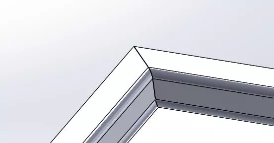
However, we want our flange to look like this:
To fix this, we need to create the part in a slightly different way.
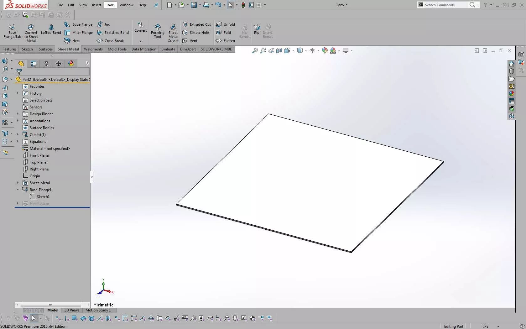
The first thing to do is create the initial sheet metal plate (the base flange in Sheet Metal) the same as you would normally.
Here’s the new process; create a sketch using one of the edges of the base flange as your sketch plane:
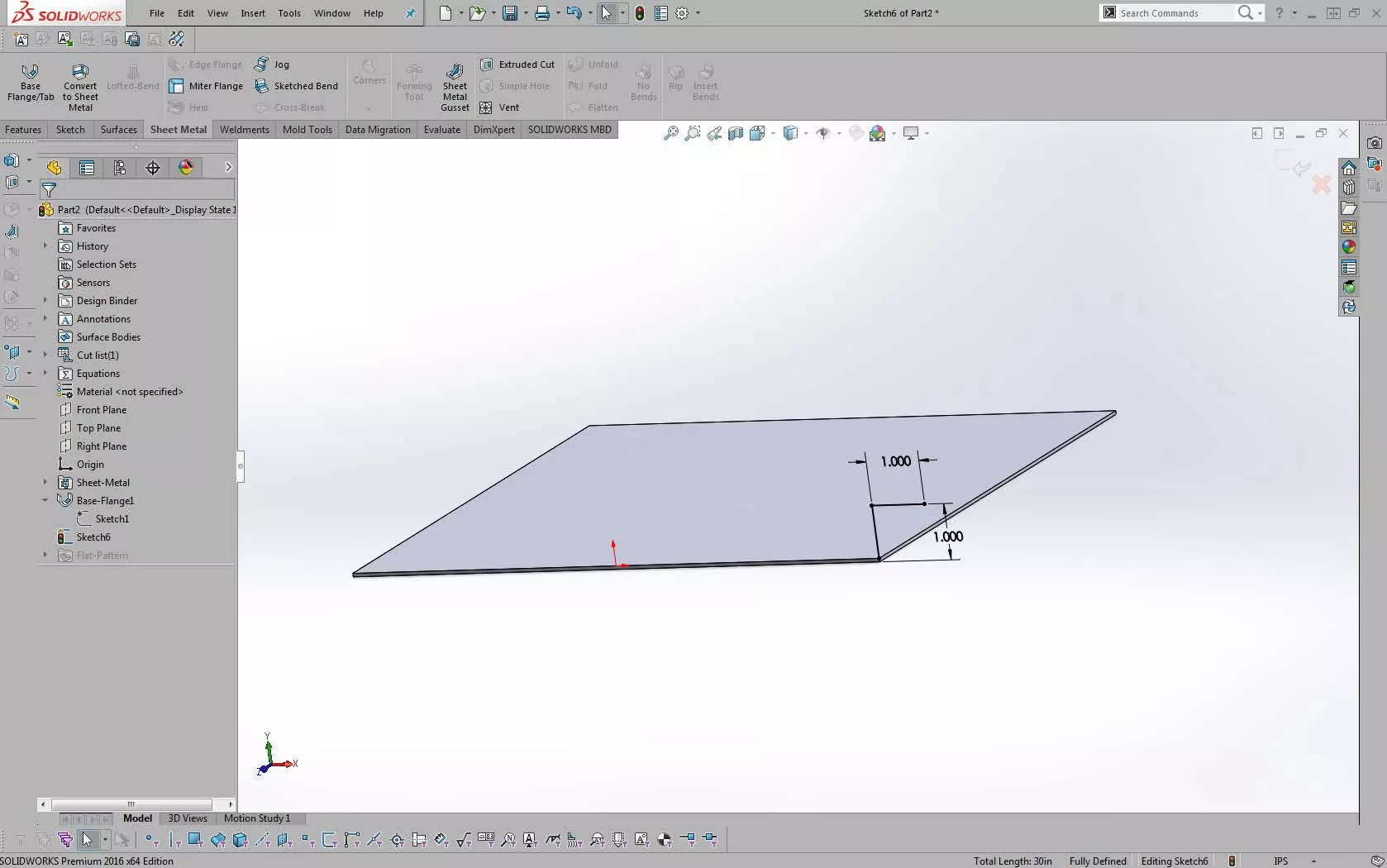
Now go directly to the Miter Flange command with this sketch:
Select all the edges of the part as needed (I selected all four for this example):
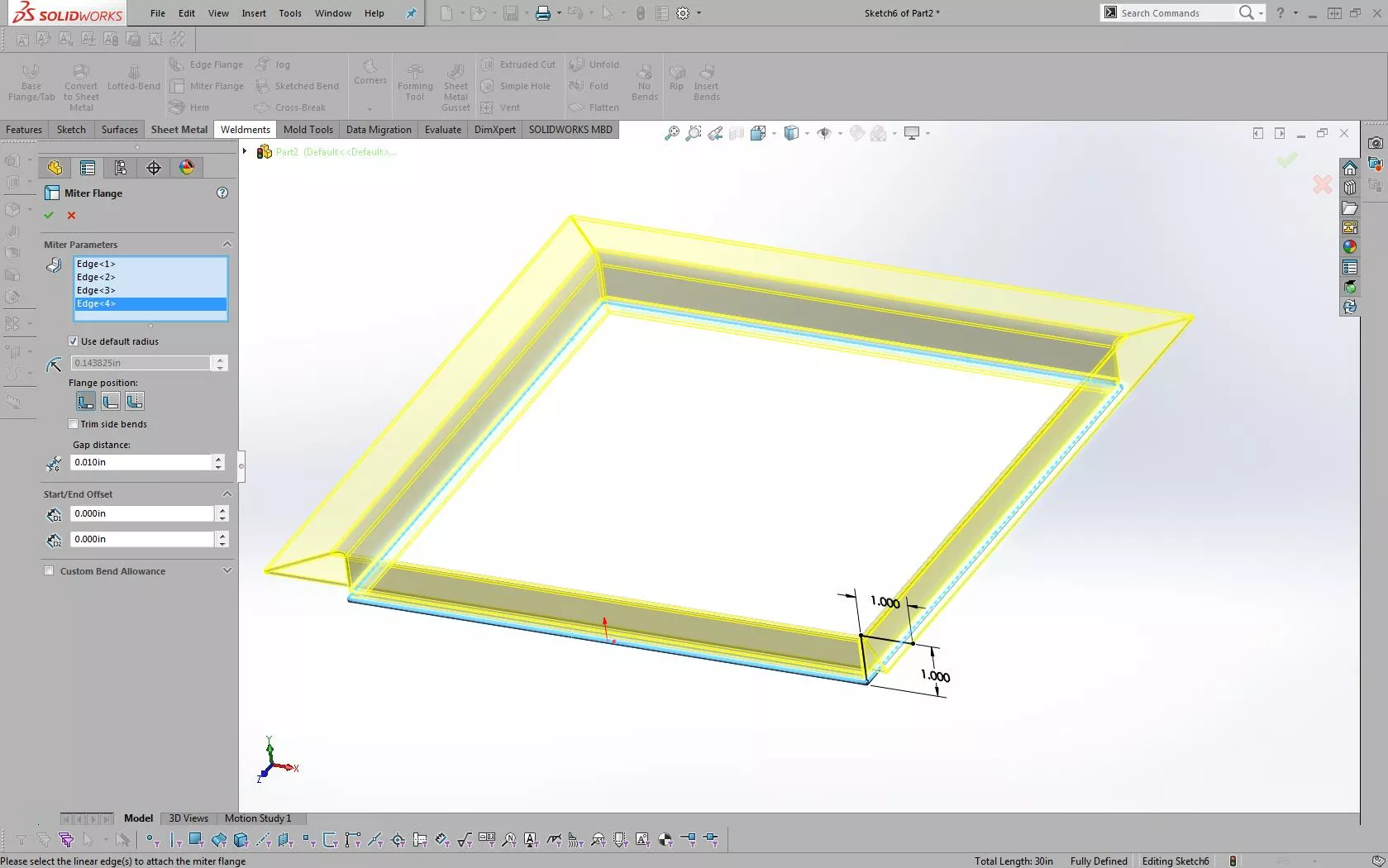
As you can see with the preview, this looks just like what we want.
Once you select the green checkmark, you should now have the completed flange.
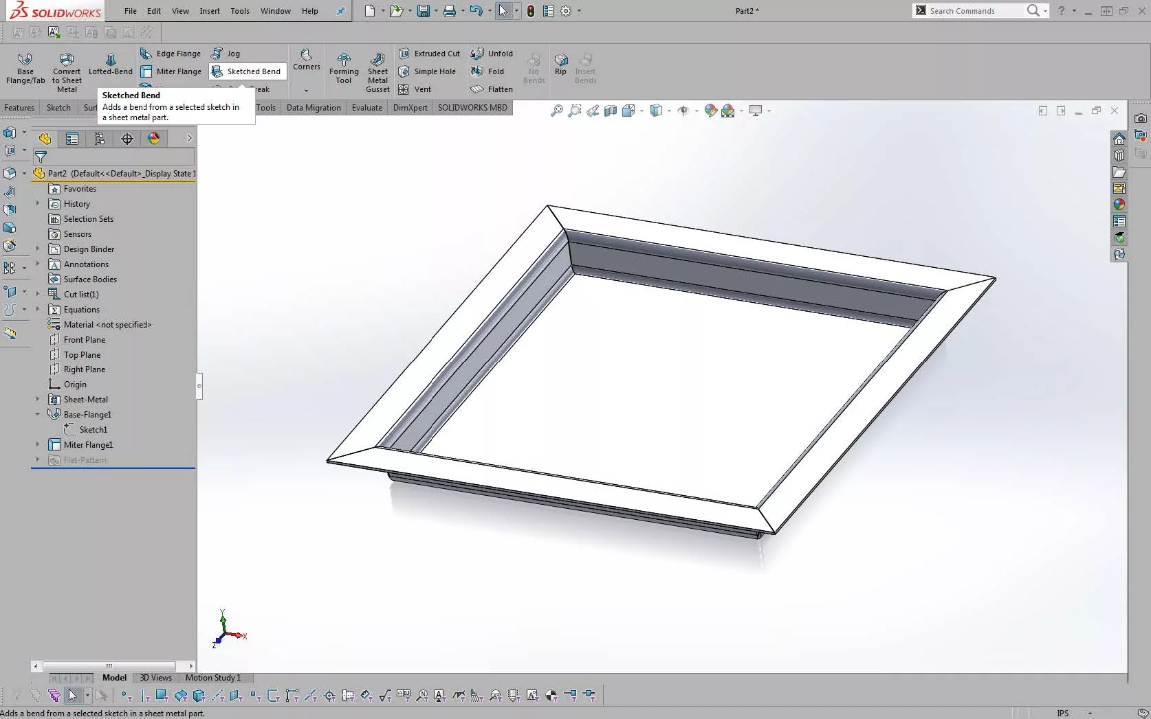
We are still making a flange for the model, but we are just making the mitered portion and the edge flange all in one step. This saves a process step in the feature tree and gives you the correct Flat Pattern configuration also:
Exterior Miter Flanges can easily be made if you follow this process.
Want to learn more? Check out more SOLIDWORKS tips and tricks below.
More SOLIDWORKS Tutorials
SOLIDWORKS Convert Sheet Metal Command Explained
SOLIDWORKS Multibody Sheet Metal Flat Pattern Drawing
SOLIDWORKS: Creating Normal Cuts in Sheet Metal
![]()
About GoEngineer
GoEngineer delivers software, technology, and expertise that enable companies to unlock design innovation and deliver better products faster. With more than 40 years of experience and tens of thousands of customers in high tech, medical, machine design, energy and other industries, GoEngineer provides best-in-class design solutions from SOLIDWORKS CAD, Stratasys 3D printing, Creaform & Artec 3D scanning, CAMWorks, PLM, and more
Get our wide array of technical resources delivered right to your inbox.
Unsubscribe at any time.