SOLIDWORKS Simulation Edge Weld Connector: Types, Sizing, & More
The edge weld connector is available in SOLIDWORKS Simulation Professional and Premium. It can be used to estimate the appropriate size of a weld needed to attach two metal components. The program calculates the appropriate weld size at each mesh node location along the weld seam. Once an analysis is completed, edge weld results can be listed and a weld check plot can be created. The edge weld connector can be defined for linear static, buckling, frequency, and linear dynamic studies.
Edge Weld Connector Definition
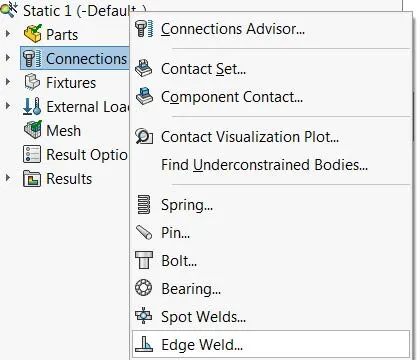
The edge weld connector definition can be accessed by right-clicking on the Connections link within the simulation study tree.
Weld Type
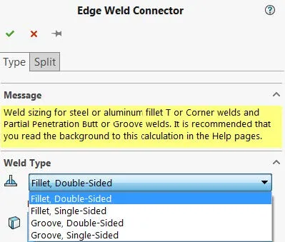
There are four weld types that can be accessed from the weld pull-down menu.
- Fillet, Double-Sided
- Fillet, Single-Sided
- Groove, Double-Sided
- Groove, Single-Sided
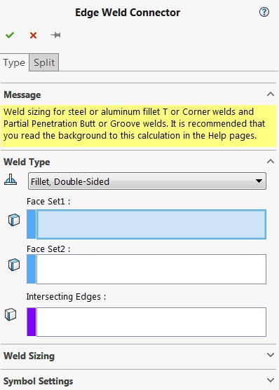
The edge weld connector can be defined between two bodies meshed using shell elements or between one body meshed using shell elements and another body meshed using solid elements. It requires three geometry selections. This includes two face sets and an intersecting edge to define the weld location.
The first face set selection has to be from a shell body whereas the second face set selection can be from a solid or a shell body. The intersecting edge has to be defined using an edge selection from the body specified in the first face set.
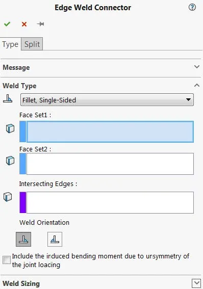
When either the Fillet, Single-Sided or Groove, Single-Sided weld types are selected, additional options are available.
There are two weld orientation options:
- Weld on Side 1
 : Positions the weld at the top surface of the shell
 - Weld on Side 2
 : Positions the weld at the bottom surface of the shell
Include the induced bending moment due to unsymmetry of the joint loading: For single-sided welds, a local eccentricity is taken into account if a tensile force is transmitted perpendicular to the longitudinal axis of the weld. In this case, the tensile force produces a bending moment at the weld throat.
Weld Sizing
Weld size calculations can be performed using two different standards.
- American Standard: based on American Welding Standard D1.1 and D1.2
- European Standard: based on Eurocode 3: Design of steel structures, Part 1.8: Design of joints, Section 4.5
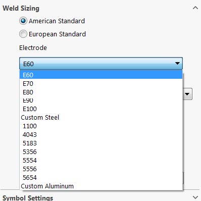
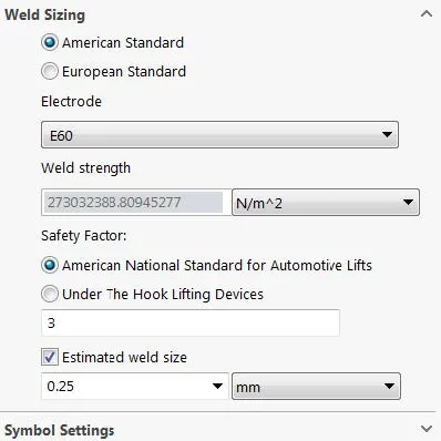
American Standard
Electrode: Sets the electrode's material. To define a material that is not listed, select Custom Steel or Custom Aluminum.
Weld Strength: Displays the selected electrode's material's ultimate shear strength. For a Custom Steel or Custom Aluminum, enter the appropriate ultimate shear strength for the weld throat.
Safety Factor: Reduces the weld's ultimate shear strength by the given safety factor (The allowable shear strength for the electrode's material is calculated as Ultimate shear strength/safety factor.)
- American National Standard for Automotive Lifts: Reduces the weld's ultimate shear strength by a default factor of 3 (ANSI/ALI B153.1-90).
- Under the Hook Lifting Devices: Reduces the weld's ultimate shear strength by a default factor of 5 (ANSI/ASME B30.20).
Estimated Weld Size: The program compares the value of the weld size in this box with the appropriate weld size and displays the results in the Weld Check Plot. For single-sided welds, the program considers their position on the side of the shell with the weakest behavior.
European Standard
Material of weaker joined part: Select the weaker part which is connected by the edge weld. The weaker part has the lesser material tensile strength. To type a custom material tensile strength, select Custom.
Ultimate Tensile Strength: Displays the selected material's tensile strength. If the material of the weaker joined part menu is set to Custom, the user needs to manually input the material tensile strength.
Correlation Factor: Enter a correlation factor between 0.8 and 1.0 for the weld calculations (see figure 1 for a list of recommended values).
Partial Safety Factor: Enter a safety factor for joints between 1.0 and 1.25 (see figure 2 for a list of recommended values).
Estimated Weld Size: The program compares the value of the weld size in this box with the appropriate weld size and displays the results in the Weld Check Plot. For single-sided welds, the program considers their position on the side of the shell with the weakest behavior.
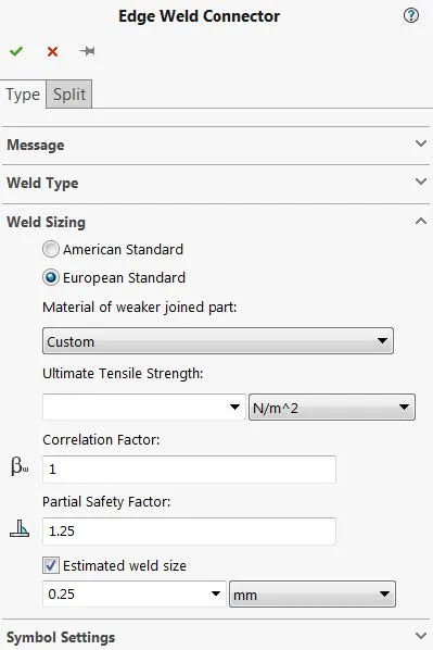
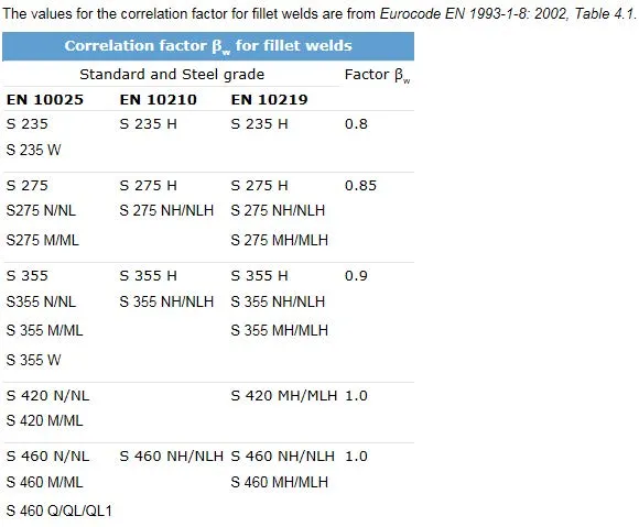
Figure 1: Recommended Correlation Factors
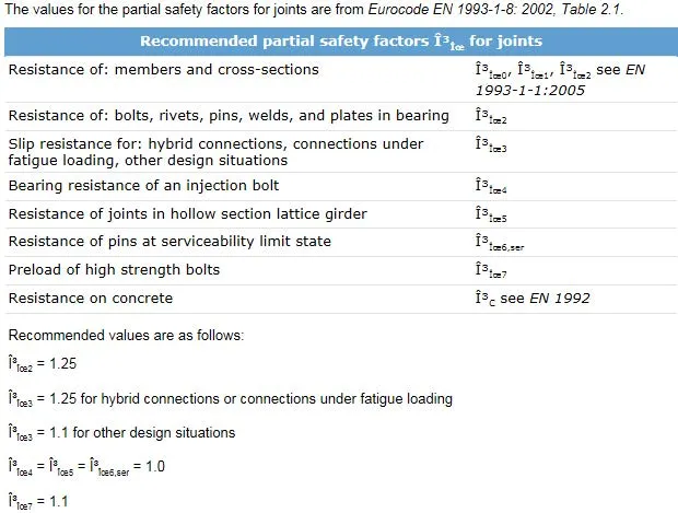
Figure 2: Recommended Partial Safety Factors
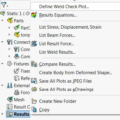
Results
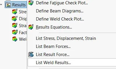
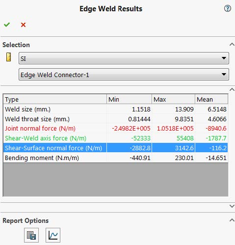
The List Weld Results dialogue can be accessed by right-clicking on the Results link in the simulation study tree. The results that are listed include the min, max, and mean values along the weld seam for the following components:
- Weld size
- Weld throat size
- Joint normal force
- Shear-Weld axis force
- Shear-Surface normal force
- Bending moment
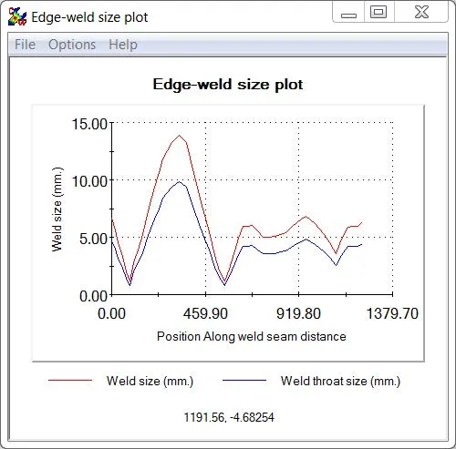
Selecting the plot option (![]() ) will display an edge-weld size plot for the selected edge weld connector. This plot displays the variation of the weld size and weld throat size along the weld seam.
) will display an edge-weld size plot for the selected edge weld connector. This plot displays the variation of the weld size and weld throat size along the weld seam.
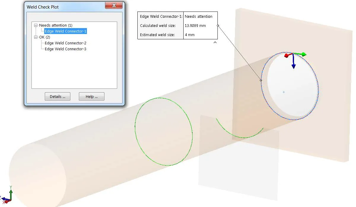
A Weld Check Plot can be created by right-clicking on the Results link in the simulation study tree. This plot will display all welds graphically with either a red or green overlay, with red indicating a weld that failed its safety check and green indicating a weld that passed its safety check. Selecting the weld in the pop-up dialogue will add a callout to the weld and display the calculated weld size versus the estimated weld size.
Learn More about SOLIDWORKS Simulation
A Guide for Using Bearing Connectors in SOLIDWORKS Simulation
SOLIDWORKS Simulation Connectors: A Primer
Frequency Study Plot with SOLIDWORKS Simulation
Offloaded SOLIDWORKS Simulation
Introduction to Structural Analysis Using SOLIDWORKS Simulation Tools
![]()
About GoEngineer
GoEngineer delivers software, technology, and expertise that enable companies to unlock design innovation and deliver better products faster. With more than 40 years of experience and tens of thousands of customers in high tech, medical, machine design, energy and other industries, GoEngineer provides best-in-class design solutions from SOLIDWORKS CAD, Stratasys 3D printing, Creaform & Artec 3D scanning, CAMWorks, PLM, and more
Get our wide array of technical resources delivered right to your inbox.
Unsubscribe at any time.