What Metal Additive Manufacturing Changes for Cutting Tool Design

Anyone who has machined titanium knows the pattern. The program is proven, the feeds are conservative, and the tool still gives out well before the plan said it would. Often the problem is not the insert grade, but that the heat has nowhere to go.
Ti-6Al-4V conducts heat at roughly 7 W/m·K, about one seventh the rate of plain carbon steel. When the chip cannot carry that heat away, it stays at the cutting edge, causing an edge that runs hot enough to lose hardness wears quickly. Nickel superalloys behave the same way.
These materials are no longer confined to aerospace. Medical, energy, and automotive shops cut them every day, and tooling engineers are being asked to do two things at once: keep the edge cool enough to hold its hardness while delivering custom tools faster than conventional machining and assembly allow.
So, what if part of the fix is not at the edge at all, but in the body itself? That is the question Bright Laser Technologies (BLT) set out to answer when it redesigned a milling cutter disc and tool holder as single printed parts on its BLT-S400. The results offer a practical reference point for what metal AM can contribute to a tooling program, and where the gains actually come from.
Common challenges
Cooling efficiency is fundamentally limited
Straight cooling channels cannot reach cutting hotspots, restricting tool life and machining performance.
Design freedom is restricted
Complex internal geometries and lightweight structures remain difficult to realize, limiting performance potential.
Small-batch production remains costly
Custom tools require dedicated tooling and multiple process steps, resulting in long lead times and high cost.
Responsiveness cannot keep up
Increasingly dynamic demand makes lead time a critical bottleneck.
Coolant designed in, not drilled in
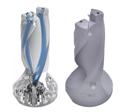
Drilled coolant passages are limited to straight lines and to wherever a drill can reach, so they are added after the tool's geometry is already set. As a result, coolant often exits near the cutting zone rather than at it.
BLT's approach reverses that order. The channels are part of the design from the start, routed to deliver coolant directly to the cutting edge. This targets keeping the edge temperature down to help the tool hold its hardness.
There is a second, less obvious benefit. Because the body and its internal channels are built together with tight dimensional control, mass is distributed more evenly around the axis, which improves balance. A better-balanced tool also gives coolant a more consistent flow direction as it spins, so the fluid goes where the channel design intended.
Lighter tools, less scrap
Machining a cutter body from solid bar stock requires two things before design even starts: how much the tool weighs, and how much material will end up as chips. For a hollow, lightweight body, much of the starting bar never makes it into the finished part.
Printing changes both of these figures. BLT's integrated milling cutter disc weighs 0.524 kg, and its tool holder weighs 0.228 kg. Because each body is built up rather than cut down, forming it creates no swarf, and unfused powder can be recovered and reused. BLT was also able to design more complex fluted geometries that would otherwise call for additional conventional machining operations thanks to additive technology’s freedom to design.
The weight reduction pays off at the spindle. Rotational inertia scales with mass times radius squared, so trimming material near the outer diameter has an outsized effect. Lower inertia means quicker acceleration and deceleration, less load on bearings and tool changers, and lower energy use every cycle. On machines with frequent tool changes, those small savings repeat thousands of times a shift.
From custom tool to production run
The usual objection to AM tooling is economic: fine for a prototype, too slow for production. For small, complex components, the numbers point the other way.
On a BLT-S400, BLT built 115 indexable drill holders (31 × 32 × 126 mm, tool steel) in a single 48-hour build, roughly 25 minutes of machine time per part. A smaller turning tool clamp fits 408 parts on one plate. The machine's 400 × 300 × 400 mm build volume and up to six lasers drive that density, and BLT designs it for low gas consumption and continuous 24/7 operation.
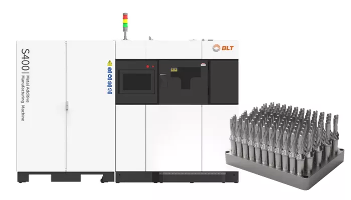
The same platform handles one-off work. With no dedicated fixturing or tooling to amortize, a tool shaped for one specific part or machine costs little more to build than a standard one, and a purpose-built tool can simplify the milling operation it serves.
A realistic expectation matters here. Printed tool bodies are near net shape, not finished parts. Heat treatment, support removal, and finish machining of locating surfaces and insert pockets are still part of the process, and they belong in the design plan from the start.
Applying this to your own tooling
The common thread in BLT's results is not the printer. It is a shift in where tool design starts: with the coolant path, the mass budget, and the material you actually need, rather than with a bar of stock.
A practical first step is to pick one tool in your current lineup that wears out early in titanium or Inconel, or one custom holder you reorder in small quantities. Model its coolant path in SOLIDWORKS Flow Simulation, run a topology study on the body, and compare the result against the current design. That gives your team a data-backed case before committing to a build.
Find the right system for your parts
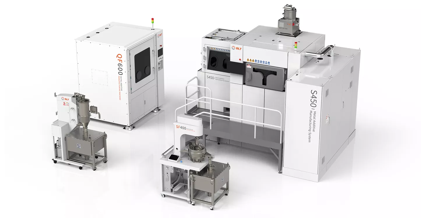
Which system and material fit your parts? GoEngineer provides BLT’s full lineup, from lab-scale machines to large-format production systems, along with the alloys each one supports.
More 3D printing news
BLT CEO Discusses What’s Now and What’s Next in Metal 3D Printing
BLT's Meter-Scale Copper 3D Printing Material for Space Propulsion
Who’s Printing the Future? Inside 10 Companies Using BLT Metal AM

About GoEngineer
GoEngineer delivers software, technology, and expertise that enable companies to unlock design innovation and deliver better products faster. With more than 40 years of experience and tens of thousands of customers in high tech, medical, machine design, energy and other industries, GoEngineer provides best-in-class design solutions from SOLIDWORKS CAD, Stratasys 3D printing, Creaform & Artec 3D scanning, CAMWorks, PLM, and more
Get our wide array of technical resources delivered right to your inbox.
Unsubscribe at any time.