SOLIDWORKS Worm Gear Mate Quick Tip
A worm drive is a gear arrangement in which a worm screw (which is a gear in the form of a screw) meshes with a worm gear (which is similar in appearance to a spur gear) to provide high-torque output from a high-speed input. This tutorial explains how to mate a worm screw and a worm gear using the gear mate feature in a SOLIDWORKS assembly.
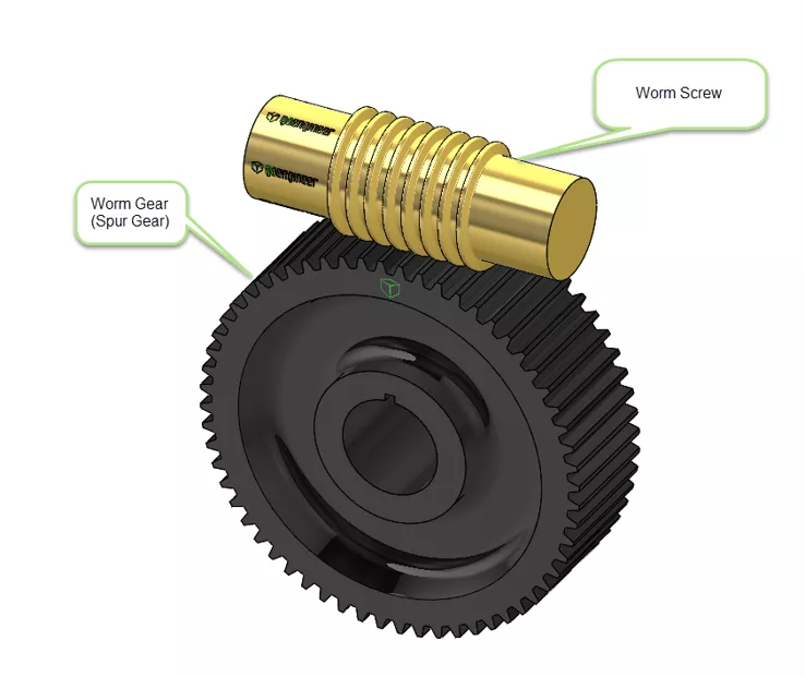
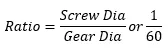
A gearbox designed using a worm screw and worm gear is considerably smaller than one made from plain spur gears and has its drive axes at 90° to each other. With a single-start worm, for each 360° turn of the worm, the worm wheel advances by only one tooth. Therefore, regardless of worm screw size, the gear ratio is the "size of the worm gear - to - 1". In the example below, I will illustrate a worm screw and a 60-tooth worm gear.
This arrangement can be found in many applications, from large heavy-duty to small light-duty.
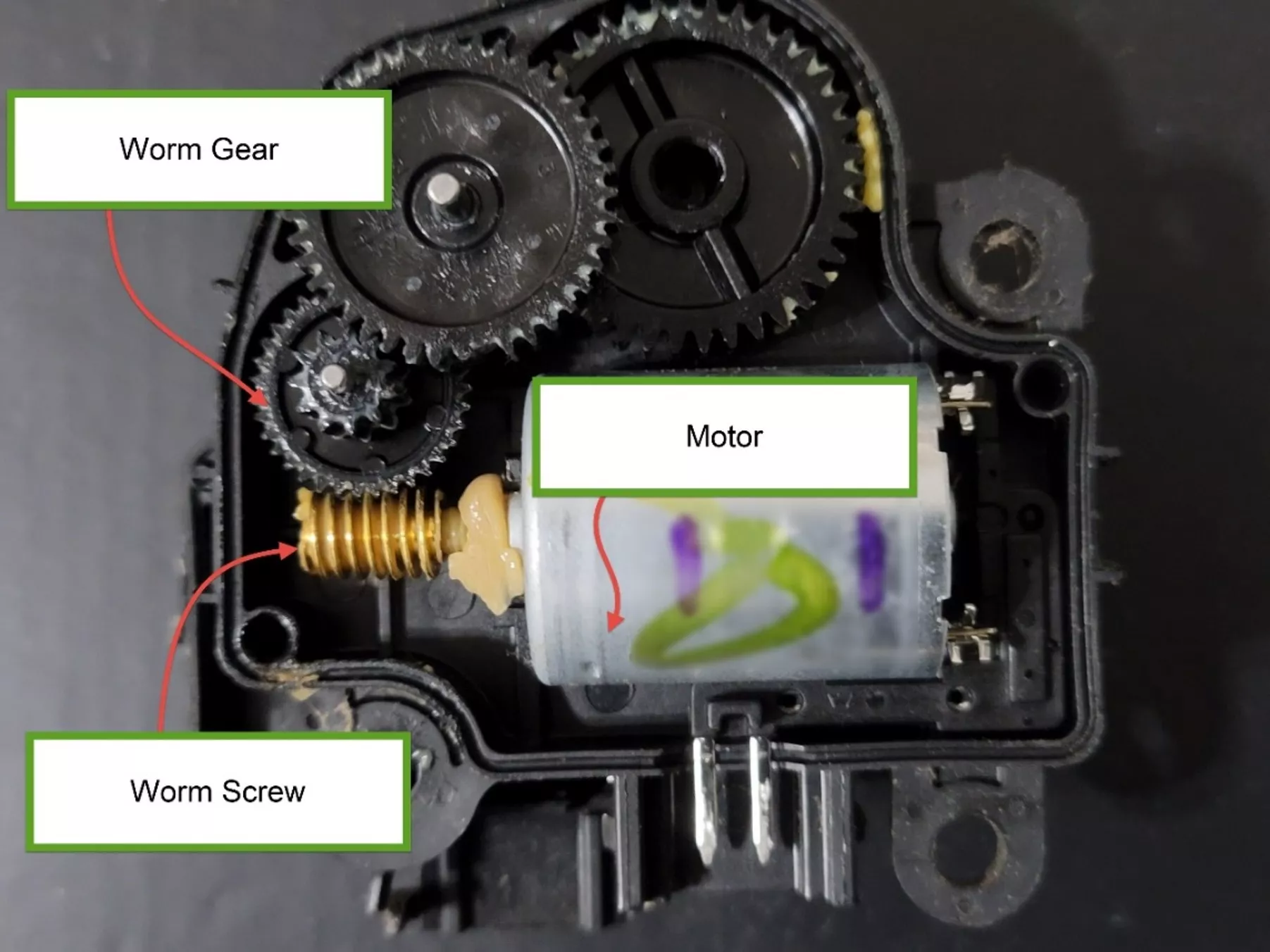
Here is one I found in an automotive HVAC positioning unit. A small DC electric motor drives a worm screw that turns a worm gear. The worm gear then advances a series of other gears to then move an output shaft on the back of the assembly, and ultimately, a baffle door in the HVAC airflow.
Let’s look at creating the mate in a SOLIDWORKS model.
Setting Up the Mate
Many SOLIDWORKS users are already familiar with gear mates. Gear mates force two components to rotate relative to one another about selected axes. Valid selections for the axis of rotation for gear mates include cylindrical and conical faces, axes, and linear edges.
You can mate any two components that you want to rotate relative to one another. You do not have to mate two gears.
Like other mate types, gear mates do not prevent interference or collisions between components. To prevent interference, use Collision Detection or Interference Detection.
To add a gear mate:
Click Mate ![]() (Assembly toolbar) or Insert > Mate.
(Assembly toolbar) or Insert > Mate.
In the PropertyManager, on the Mechanical tab, click Gear ![]() .
.
Under Mate Selections, select the rotation axes on the two gears for Entities to Mate ![]() .
.
Under Mate Type:
| Option | Description |
| Ratio | The software assigns gear ratios based on the relative sizes of the cylindrical faces or circular edges you select. The values are parametric. You can override the values. To revert to the default value, delete the override value. The background color of the box is white for the default value, and yellow for the override value. |
| Reverse | Select Reverse to change the direction of rotation of the gears relative to one another. |
Click the green checkmark to complete the mate.
The key element here is that the worm screw is set to one and the worm gear set to the number of teeth. This will establish the correct ratio, even though the actual diameters of the entities I selected differ. The circular edges used are not the determining factor; rather, the ratio is.
I have simplified that type of arrangement for better illustration. Here, I have selected the mate feature after selecting the shaft on the worm screw and a circular edge on the worm gear.
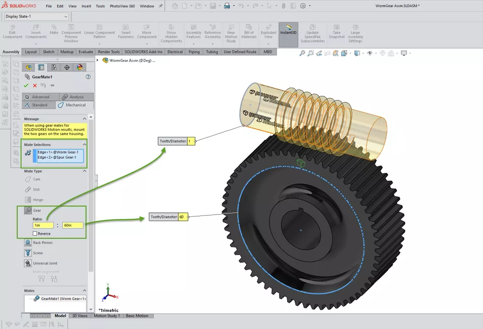
In the ratio inputs, I have set 1 for the worm screw and 60 for the worm gear.
In this assembly, I have also created five configurations with the worm screw rotated from 0° to 360° in 90-degree increments. As I step through each one, you can see the resulting movement highlighted on the worm gear.
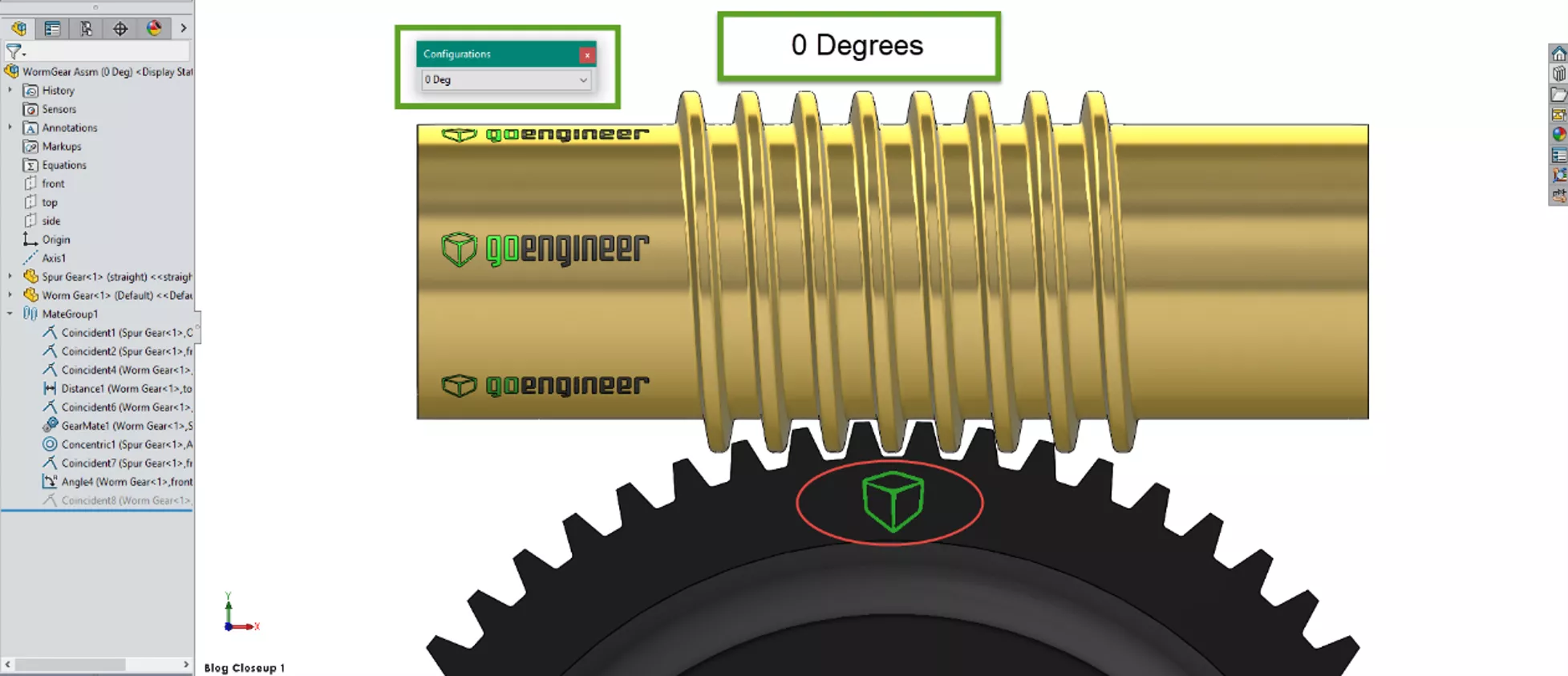
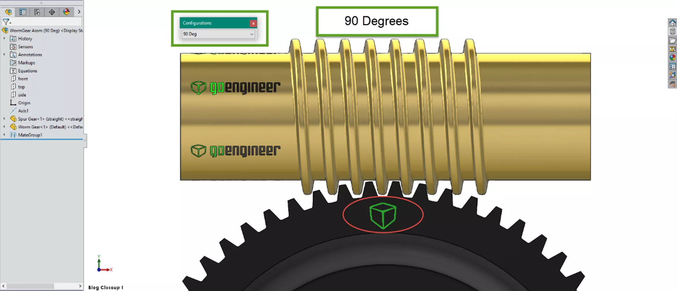
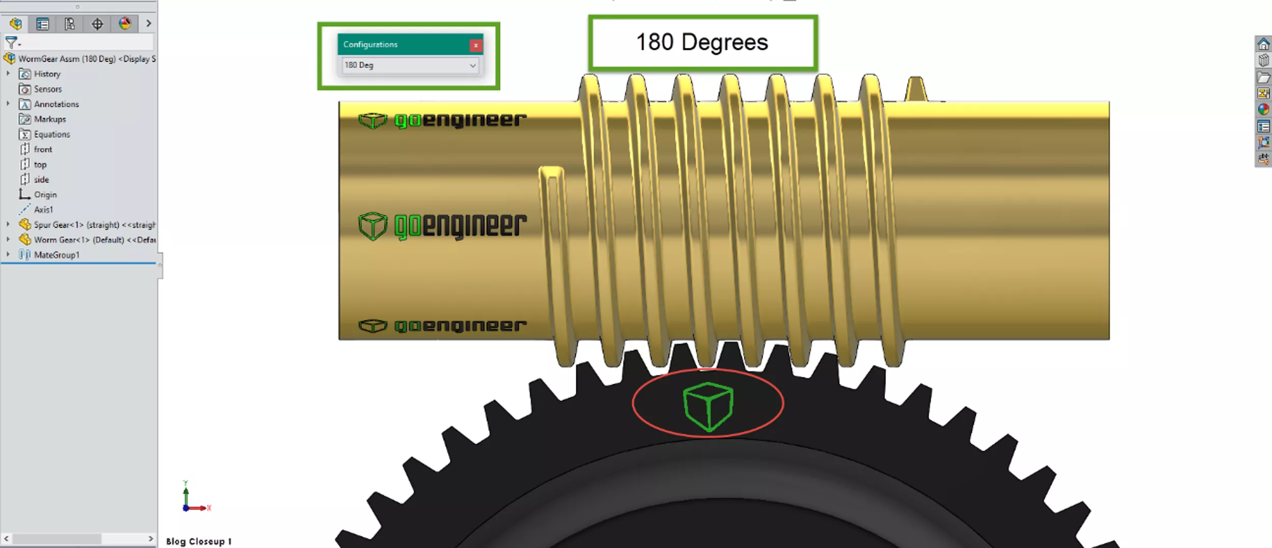
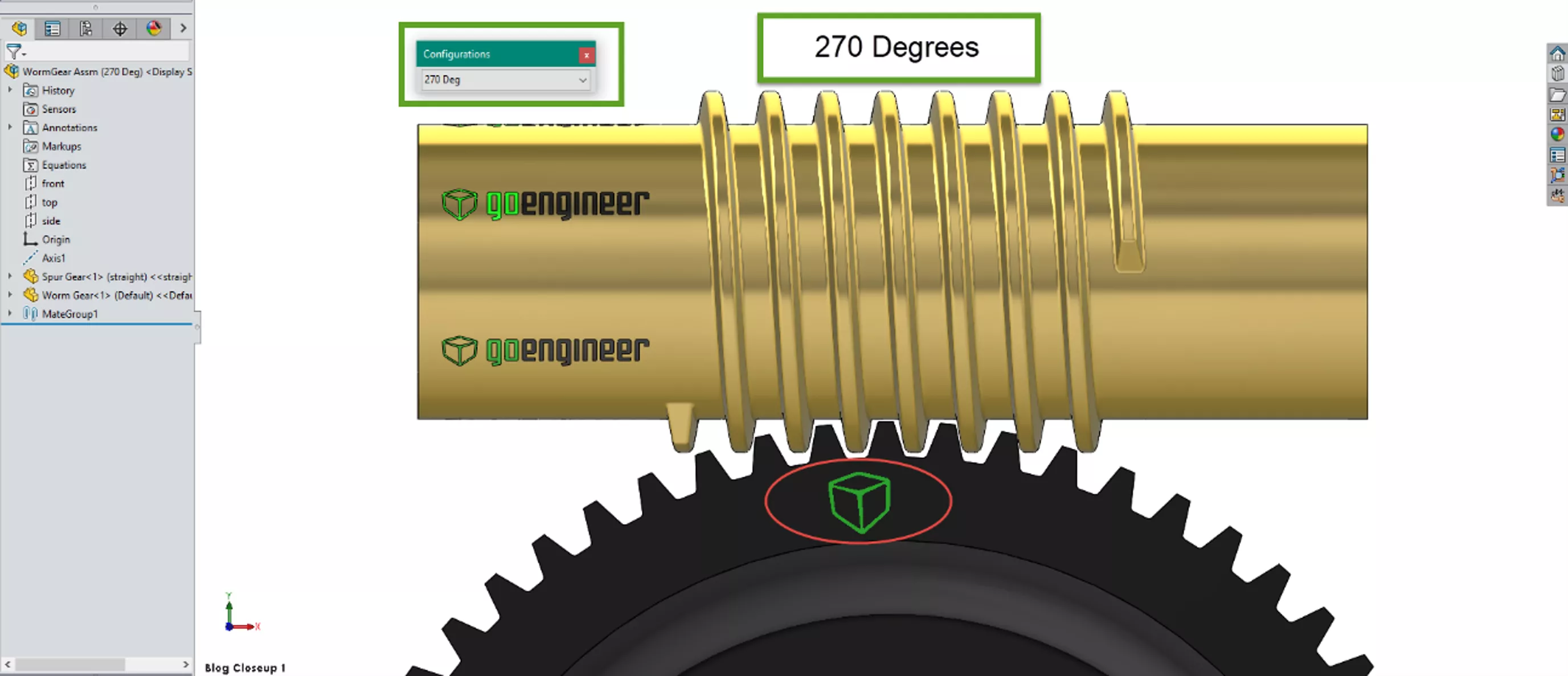

After a full 360° on the worm screw, the worm gear has moved by one tooth. Releasing the angular mate I applied on the worm screw will now allow another input to the worm screw to freely turn the worm gear.
SOLIDWORKS CAD Cheat Sheet
SHORTCUTS ⋅ MOUSE GESTURES ⋅ HOT KEYS
Our SOLIDWORKS CAD Cheat Sheet, featuring over 90 tips and tricks, will help speed up your process.

Want to learn more about SOLIDWORKS? Check out more tutorials and tips below, or check out the GoEngineer Community, where you can create forum posts, enter design contests, and answer questions from other SOLIDWORKS users.
Related Articles
Missing SOLIDWORKS Bend Lines in Flat Pattern DXF
Changing Component Colors in SOLIDWORKS Drawings
Modeling Conveyor Belts with Cleats in SOLIDWORKS
Intro to SOLIDWORKS Sketch Blocks
![]()
About Martin Adams
Martin Adams is a Senior Technical Support Engineer at GoEngineer supporting SOLIDWORKS CAD and SOLIDWORKS Electrical products. In addition to a CSWE certification, he has a Bachelor's degree in Industrial Engineering and an Electrical Associate's degree. Prior to joining GoEngineer in 2019, he worked for almost twenty years on prototype automotive instrumentation. He also served as an Electrician's Mate in the US Navy. His favorite activities are fishing and spending time around a campfire with friends.
Get our wide array of technical resources delivered right to your inbox.
Unsubscribe at any time.