Using Section Scope to Customize Section Views in a SOLIDWORKS Drawing

Have you ever needed to show full components in a section view or remove some hatching in a drawing? If so, there are a few handy tricks to achieve this using the Section Scope feature in SOLIDWORKS.
Accessing Section Scope
The Section Scope tab appears automatically when you create a section view.
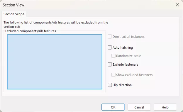
If the Section View has already been created, you can right-click the Section View, select Properties, then select the Section Scope tab.
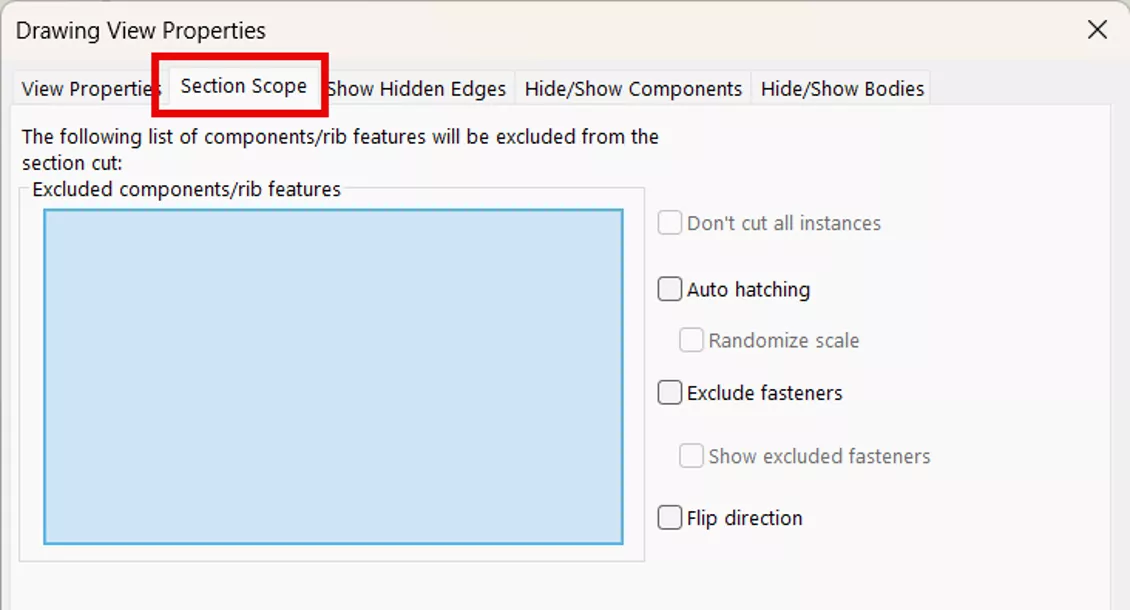
In the Section Scope dialog box or tab from the Drawing View Properties, there are several options to customize the section view. We can exclude components/rib features, cut all instances of duplicate components, auto-hatch the view, exclude fasteners, and flip its direction.
Excluding Components/Rib Features and Fasteners
Selecting Components/Rib Features from the Drawing’s Section View
Components that you select while this dialog is open appear in the blue Excluded components/rib features field. Components and rib features can be selected directly from the drawing view.
Example
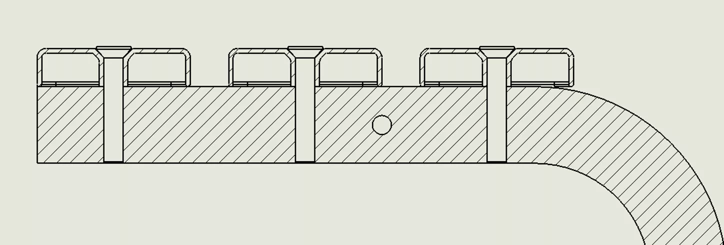
In this example, I've selected 3 screws from the drawing view. After clicking OK in the Properties dialog box, the screws are no longer hatched, indicating they are no longer being sectioned.
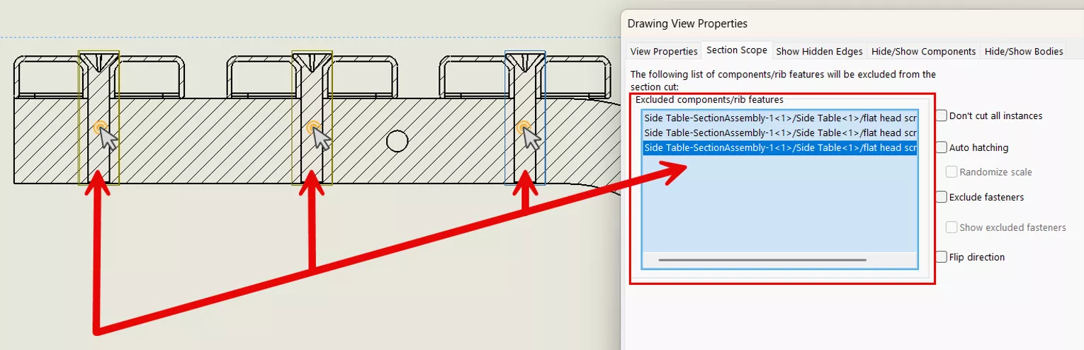
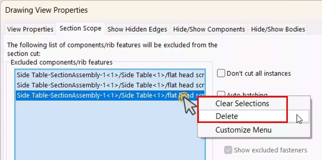
To remove a component from the list, you can deselect it from the drawing view, or right-click on the component in the Excluded components/rib features field and select Delete. To remove all components from the excluded list, select Clear Selections.
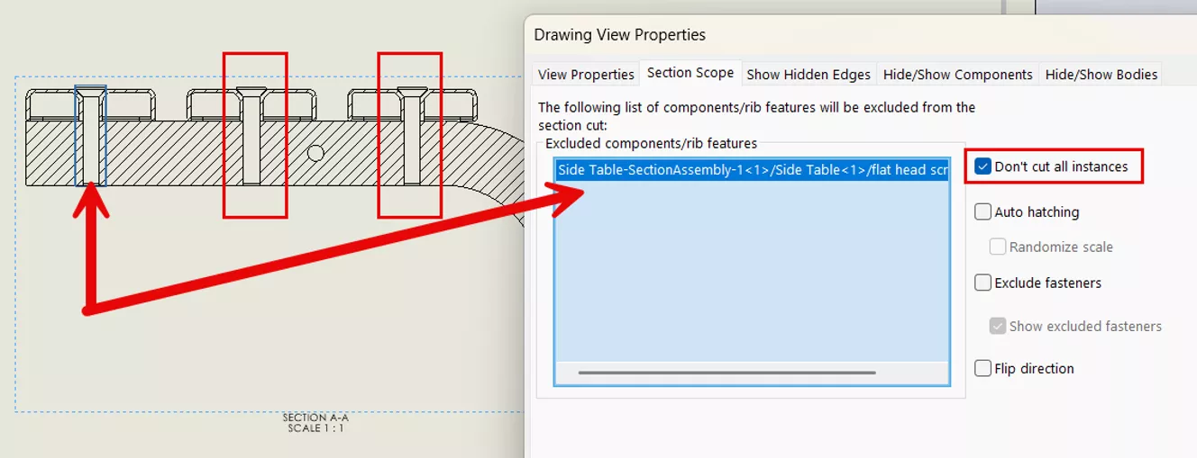
By default, all instances of a selected component will be sectioned. Tick the option Don’t cut all instances if you'd prefer to only section/cut those instances you've specifically added to the Excluded components field.
Assigning a Fastener “Tag” to a Component
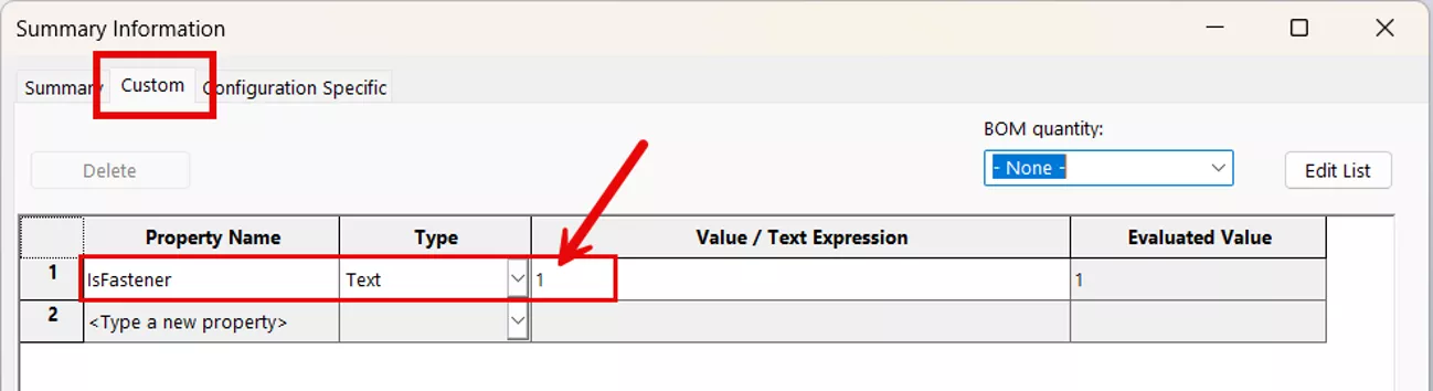
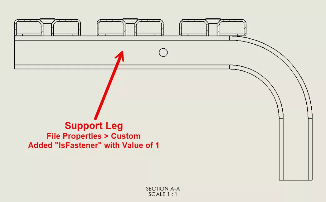
The option Exclude fasteners is a quick, fairly self-explanatory way to handle standard hardware. To manually define a component as a fastener, add the "IsFastener" property to its File Properties.
- Open the component or fastener.
- Go to File > Properties, then select the Custom tab.
- Add a new property named “IsFastener”, and set the Value/Text Expression to ‘1’.
- Rebuild (Ctrl+Q) and save the file.
- Go back to the drawing.
- Right-click on the section view and select Properties, then click the Section Scope tab.
- Check the Exclude fasteners option.
- Optionally, click Show excluded fasteners to preview those fasteners.
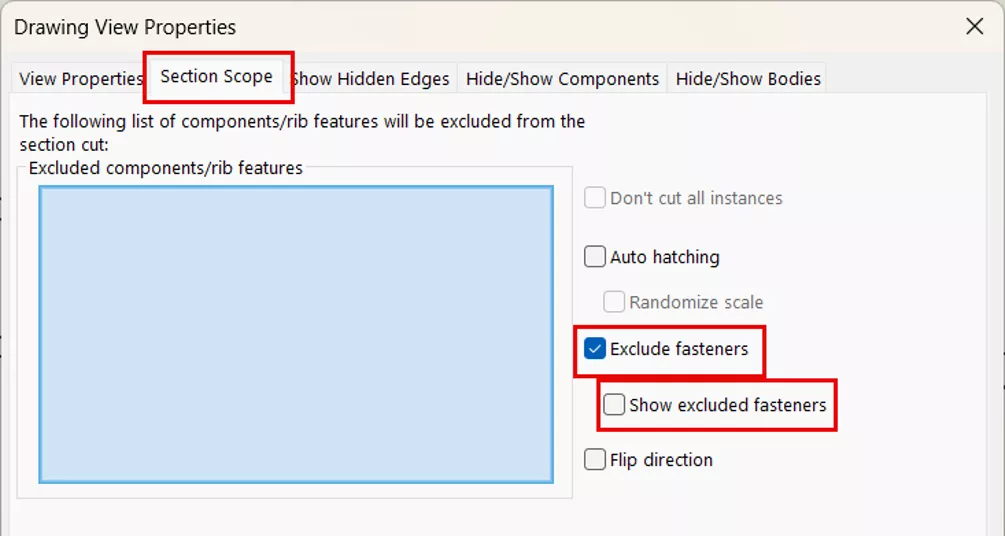
- Optionally, click Show excluded fasteners to preview those fasteners.
Example
In this example, I added the “IsFastener” property with a value of ‘1’ to my “Support Leg” part. Afterward, when checking the Exclude fasteners in the Section Scope tab, it was no longer sectioned in the drawing section view.
Hatching Options in a Section View
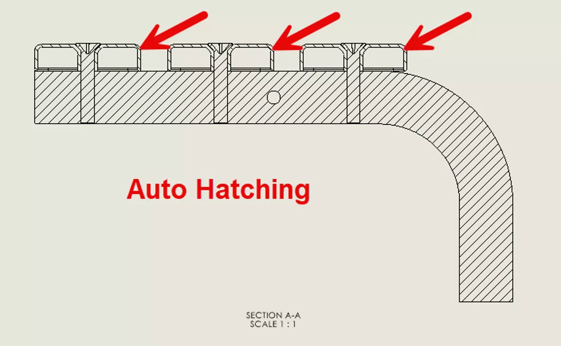
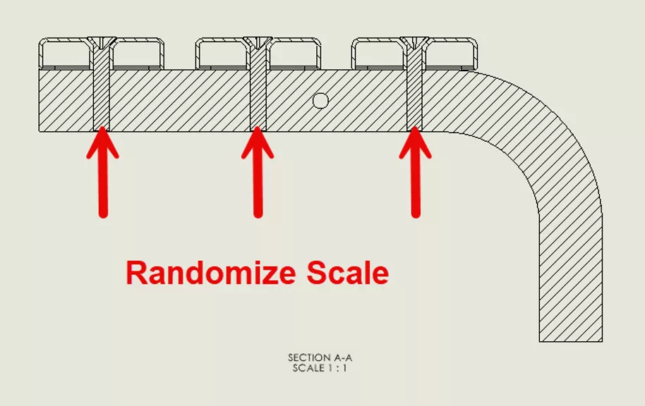
In the Section Scope tab, you can also control how the cross-hatch appears in the section view. The Auto hatching option changes the angle of the cross-hatch between adjacent cut faces. Below it, the Randomize Scale option changes the size of the hatch for components in the drawing view that have the same material.
Hatching Options in a Section View
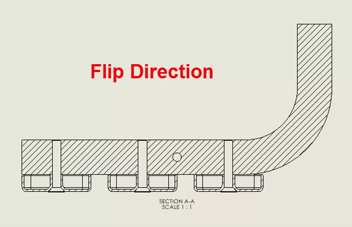
The last option, Flip direction, is self-explanatory. Checking this will reverse the direction of the section view.
Conclusion
Customizing the Section Scope options allows section views to better communicate details in SOLIDWORKS drawings. Hopefully this introduction helped to familiarize you with these techniques.
SOLIDWORKS CAD Cheat Sheet
SHORTCUTS ⋅ MOUSE GESTURES ⋅ HOT KEYS
Our SOLIDWORKS CAD Cheat Sheet, featuring over 90 tips and tricks, will help speed up your process.

To learn more about SOLIDWORKS drawings, check out the articles listed below. Additionally, join the GoEngineer Community to participate in discussions, create forum posts, and answer questions from other SOLIDWORKS users.
Related Articles
SOLIDWORKS 2026 Drawings - What's New
Why Your SOLIDWORKS Drawing Balloons Have Question Marks (?) or Asterisks (*)
SOLIDWORKS Drawing View Labels Explained
Applying a New SOLIDWORKS Drawing Sheet Format to Existing & Future Drawings

About Tashayla Openshaw
Tashayla Openshaw is a SOLIDWORKS Technical Support Engineer based out of our Headquarters in Salt Lake City, Utah. She earned her Bachelor’s degree in Mechanical Engineering from the University of Utah in 2018 and has been part of the GoEngineer family since February 2019.
Get our wide array of technical resources delivered right to your inbox.
Unsubscribe at any time.