Flattened vs. Folded Mass Properties in SOLIDWORKS Sheet Metal Parts

This article examines mass properties in SOLIDWORKS sheet metal parts and discusses why they may differ between folded and flattened configurations.
What Changes When Sheet Metal is Folded?
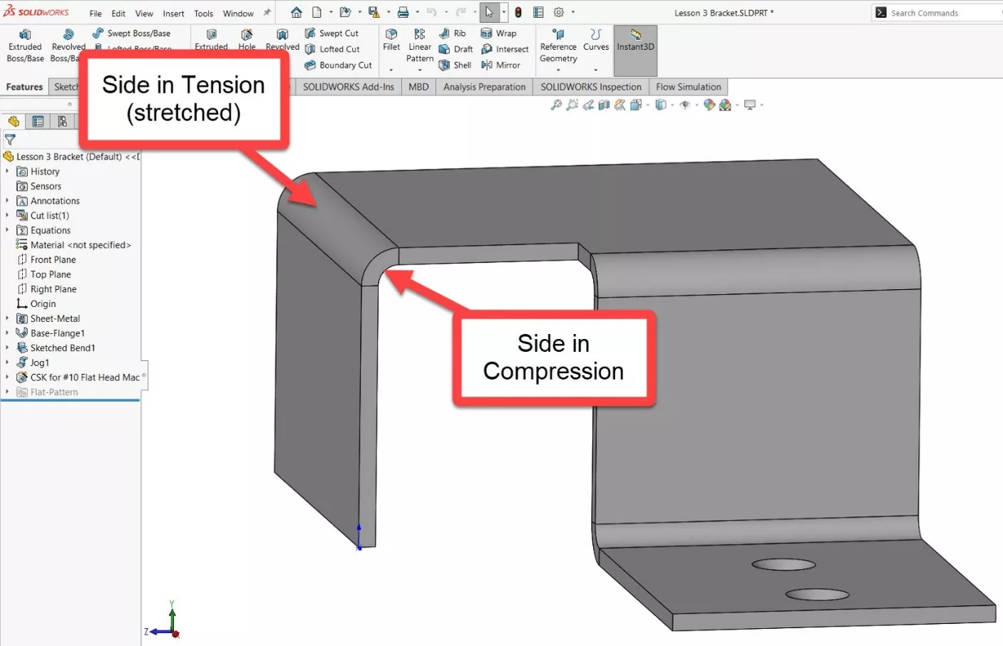
When sheet metal is folded, the outside of the bend is under tension, and the inside of the bend is compressed. Think of it like bending a garden hose—the inside bulges while the outside is stretched and becomes taut. The same thing happens to metal parts, just to a lesser degree.
Why This Happens
Because the material must take a permanent bend (known as plastic deformation), it is pushed to its yield strength. This causes the side in tension to permanently stretch. In order for it to become longer, however, it also must get thinner. How much thinner? This is directly related to Poisson’s Ratio, which is equal to the lateral strain divided by the axial strain. In other words, how thin it gets over how long it gets. A high value for this ratio means the material gets a lot thinner (and stretches a lot more). This is more apparent in ductile materials like aluminum, but it also happens in steel.
Why This Matters
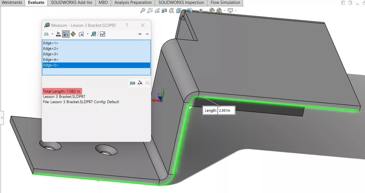
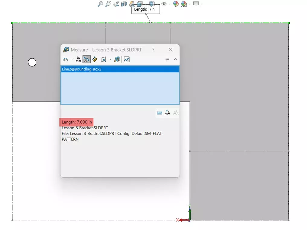
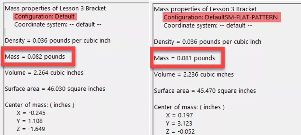
This means that when you fold a sheet metal part, it gets longer. The bend region becomes thinner, which changes the mass distribution of the part - but not the total mass. This is true both in theory and in practice, but not necessarily in SOLIDWORKS. To simplify the mass calculation, SOLIDWORKS treats the bent part as if it were the same thickness throughout the entire bend region. It does calculate the length of the stretch, which is crucial for forming accurate parts, but as a result, it gives a higher mass for the folded part. Because of this, the mass shown for the flattened part is correct, but the mass for the folded part isn’t always accurate.
Using the K-Factor as a Workaround
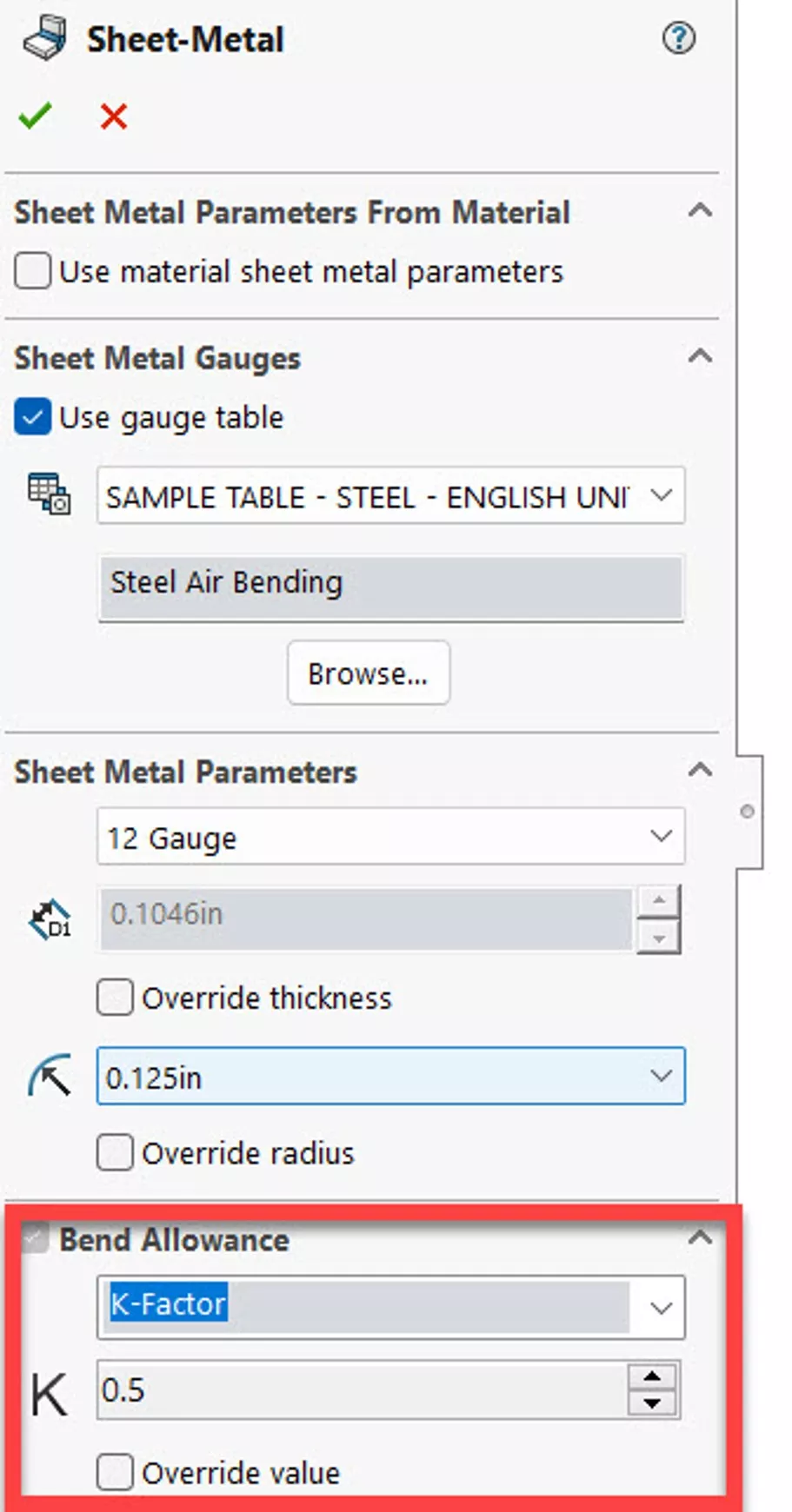
The K-factor of a sheet metal part is essentially where the neutral axis is through the bend region. The axis is the theoretical arc inside the bend where the material is neither in compression nor tension - it’s where the material transitions between them.
It’s calculated by dividing the thickness of the compression side by the total thickness of the unbent part. If the K-factor is set to 0.5, it places the neutral axis in the exact center of the material, causing the compressed side to be equal to the stretched side. This means the total length of the part isn’t changing, which causes the folded mass and flattened mass to appear the same inside SOLIDWORKS.
Be careful using this strategy, however, as few materials will have a K-factor of 0.5 in real life. Most are somewhere between 0.25 and 0.45 for folding operations, and getting this wrong can lead to inaccurate dimensions in the folded part. It’s generally recommended to reference the mass of the flat pattern when an accurate mass is needed from SOLIDWORKS.
To learn more, check out the articles listed below. Additionally, join the GoEngineer Community to participate in discussions, create forum posts, and answer questions from other SOLIDWORKS users.
SOLIDWORKS CAD Cheat Sheet
SHORTCUTS ⋅ MOUSE GESTURES ⋅ HOT KEYS
Our SOLIDWORKS CAD Cheat Sheet, featuring over 90 tips and tricks, will help speed up your process.

More SOLIDWORKS Sheet Metal Tips
Show Sheet Metal Bend Lines in a SOLIDWORKS Drawing
SOLIDWORKS Sheet Metal Sketched Bend Tutorial
SOLIDWORKS Convert to Sheet Metal vs Insert Bends
SOLIDWORKS Convert to Sheet Metal Command Explained

About GoEngineer
GoEngineer delivers software, technology, and expertise that enable companies to unlock design innovation and deliver better products faster. With more than 40 years of experience and tens of thousands of customers in high tech, medical, machine design, energy and other industries, GoEngineer provides best-in-class design solutions from SOLIDWORKS CAD, Stratasys 3D printing, Creaform & Artec 3D scanning, CAMWorks, PLM, and more
Get our wide array of technical resources delivered right to your inbox.
Unsubscribe at any time.