Using the SOLIDWORKS Sheet Metal Jog Feature

The Jog feature in SOLIDWORKS Sheet Metal allows you to create an offset bend in an existing sheet metal part by defining a bend line and specifying the jog dimensions. This can be useful when adding clearance for mating components, creating stepped profiles, or modifying a design to meet manufacturing requirements. In this article, we'll walk through how to use the Jog feature and explain the available options so you can quickly add jogs to your sheet metal designs.
Accessing the Jog Command
Before creating a jog, we'll first need to locate the command in the SOLIDWORKS interface. The Jog feature is available in the Sheet Metal CommandManager tab. Alternatively, it can be accessed by selecting Insert > Sheet Metal > Jog from the menu bar.

How to Create the Jog Feature
In this example, we will use the Jog feature to create three different offsets in a sheet metal part. These jogs will demonstrate how the feature can be used to modify the shape of a part by creating additional bends and offsets in the sheet metal body. The following steps will walk through creating each jog and adjusting the available options to achieve the desired results.
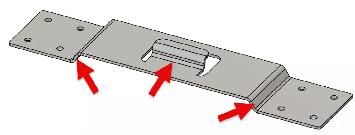
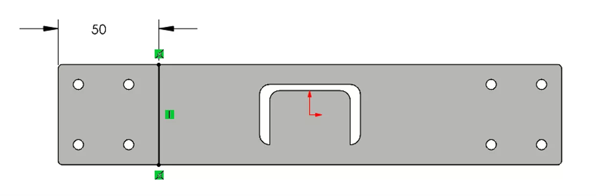
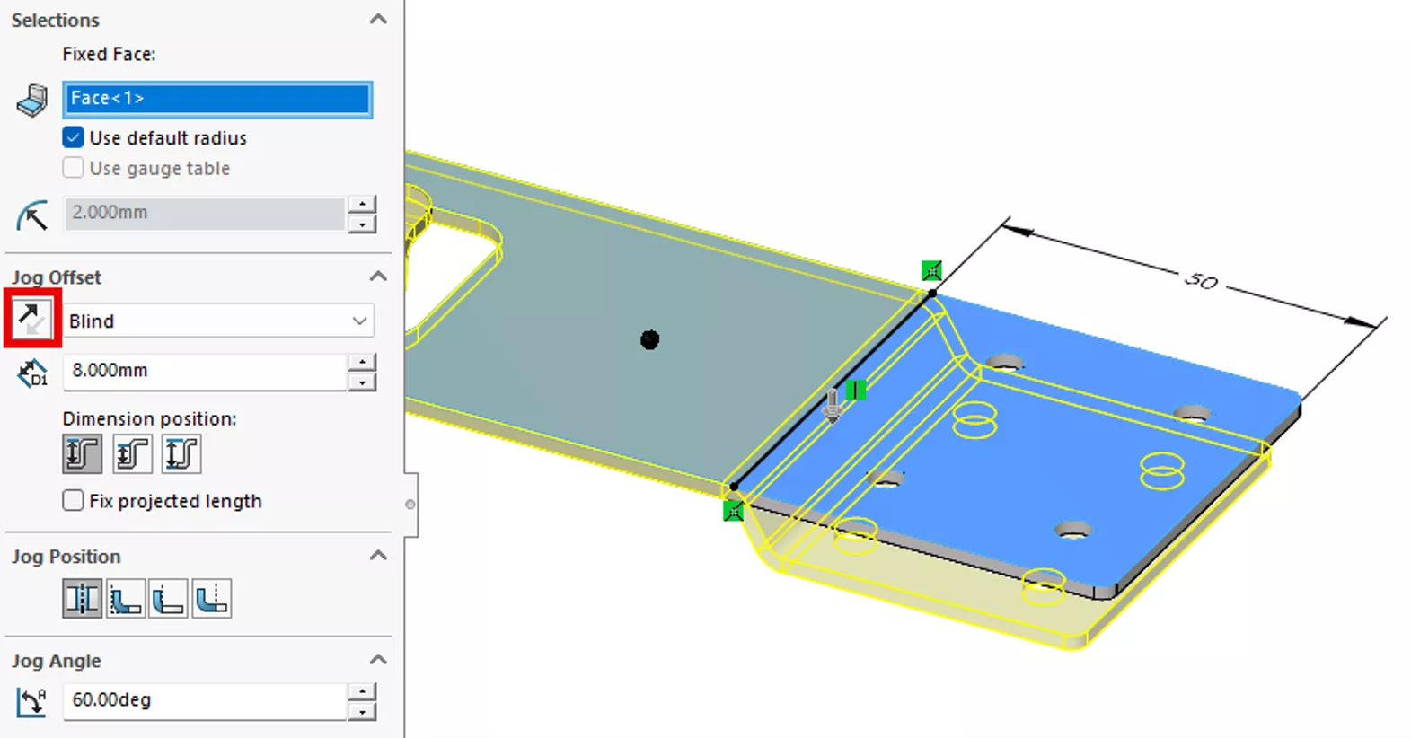
We will begin with a flat sheet metal part that does not contain any existing bends. The first jog will be created on the left side of the part. To define the location of the jog, start by creating a sketch on the top flat face of the sheet metal body. Draw a sketch line across the part and dimension it 50 mm from the left edge, as shown in the image below.
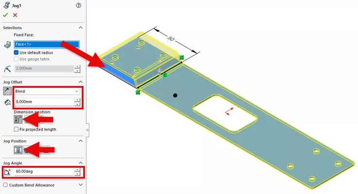
With the sketch still active, launch the Jog feature and select the top flat face of the sheet metal part as the Fixed Face. Under the Jog Offset section, set the end condition to Blind and define the offset distance as 8 mm. For the Dimension Position, select Outside Offset. Next, we'll set the Jog Position to Bend Centerline, enter a Jog Angle of 60 degrees, and click OK to complete the first jog.
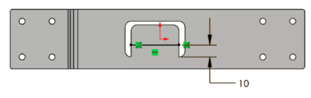
For the second jog, we'll focus on the tab located within the center cutout of the sheet metal part. This tab provides the area where the next jog will be created. Let's begin by starting a new sketch on the top face of the part and creating a horizontal sketch line. The line will be positioned 10 mm from the bottom edge of the cutout, which will define the location of the second jog.
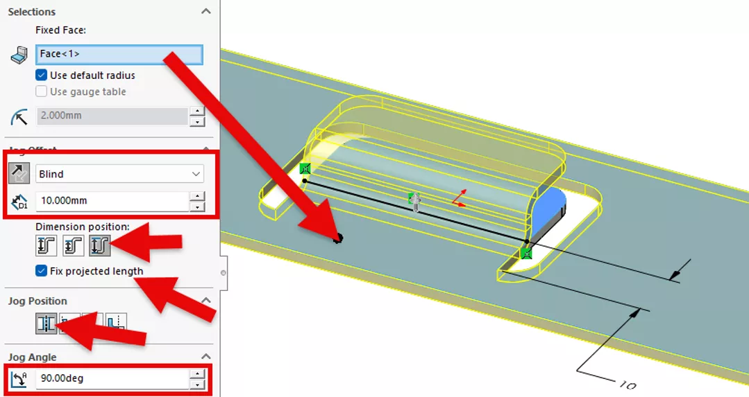
With the sketch still active, launch the Jog feature and select the top face of the part as the Fixed Face. Under Jog Offset, set the end condition to Blind, make sure the jog is going up, and enter 10 mm.
For the Dimension Position, we'll select Overall Dimension and enable Fix projected length. The Jog Position will remain set to Bend Centerline, and we'll set the Jog Angle to 90 degrees. Once the settings are defined, click OK to create the second jog.
If we look at the flat pattern, we can see there is a problem with the jog we just created. The jog material extends into the rest of the flat pattern, meaning the jog operation added more material to the tab in the middle of the cutout.
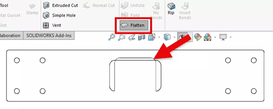
The jog's overall dimension needs to remain unchanged while ensuring the tab length is maintained. This allows the sheet metal part to unfold correctly when creating the flat pattern. To achieve this, we'll edit the newly created Jog feature and disable the Fix projected length option.
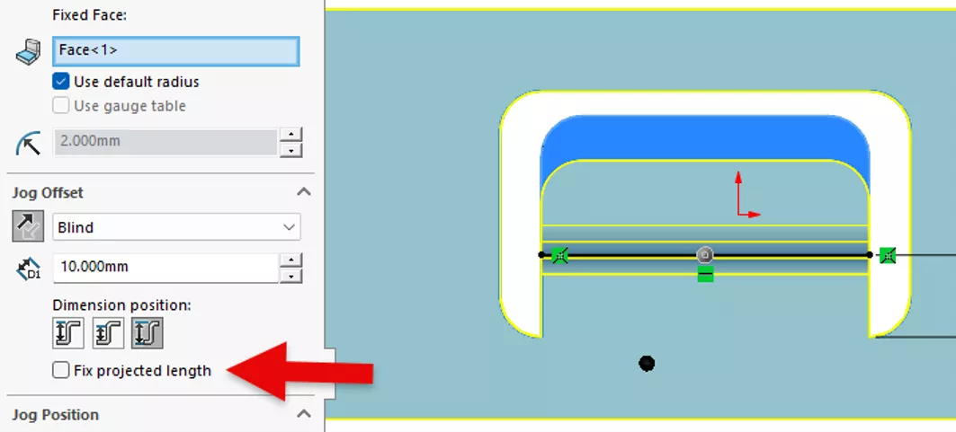
When enabled, this option maintains the projected length of the part based on the entered jog values. With the option cleared, the feature instead preserves the actual length of the existing tab geometry, which, in this case, maintains the length of the tab when flattened.
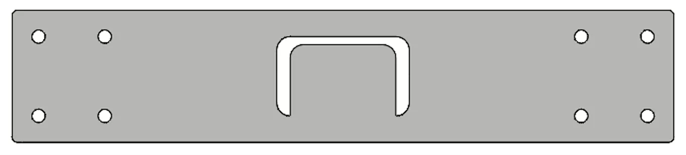
For the final jog, we'll create the feature on the right end of the sheet metal part using the same process as the first jog. Let's begin by creating a sketch on the top face and adding a sketch line to define the jog location. Once the sketch is complete, use the Jog feature to create the offset, applying the appropriate jog settings to match the desired geometry. This will complete the three jogs demonstrated in the example part.
Summary
The Jog feature in SOLIDWORKS provides a simple and effective way to create offset bends in sheet metal parts while maintaining control over the resulting geometry. By adjusting options such as jog direction, offset distance, bend position, and projected length settings, we can create precise features that meet design requirements while ensuring the part unfolds correctly in the flat pattern.
SOLIDWORKS CAD Cheat Sheet
SHORTCUTS ⋅ MOUSE GESTURES ⋅ HOT KEYS
Our SOLIDWORKS CAD Cheat Sheet, featuring over 90 tips and tricks, will help speed up your process.
To learn more about SOLIDWORKS sheet metal, check out the articles listed below. Additionally, join the GoEngineer Community to participate in discussions, create forum posts, and answer questions from other SOLIDWORKS users.
Related Articles
SOLIDWORKS Convert to Sheet Metal vs Insert Bends
SOLIDWORKS Sheet Metal Lofted Bend Manufacturing Methods Bent & Formed
SOLIDWORKS Sheet Metal: Export Flat Pattern to DXF File
SOLIDWORKS Costing: Sheet Metal Parts
Display SOLIDWORKS Sheet Metal Surface Area in Your Bill of Materials

About Zach Brown
Zach Brown is a certified SOLIDWORKS Expert and a Technical Support Engineer. Prior to working at GoEngineer, he spent 15 years as a mechanical designer, CAD support tech, and instructor using SOLIDWORKS. His hobbies include playing guitar, riding motorcycles, and skiing.
Get our wide array of technical resources delivered right to your inbox.
Unsubscribe at any time.