Create a SOLIDWORKS Model From a Picture

Sometimes, a photograph and a few dimensions are all you need to create a 3D SOLIDWORKS model of an existing object. 3D scanners are great for capturing depth and 3D curves, but for something like a flat pattern of a sheet metal part, a phone and a digital caliper will usually do.
Using Sketch Picture to Create a 3D Model
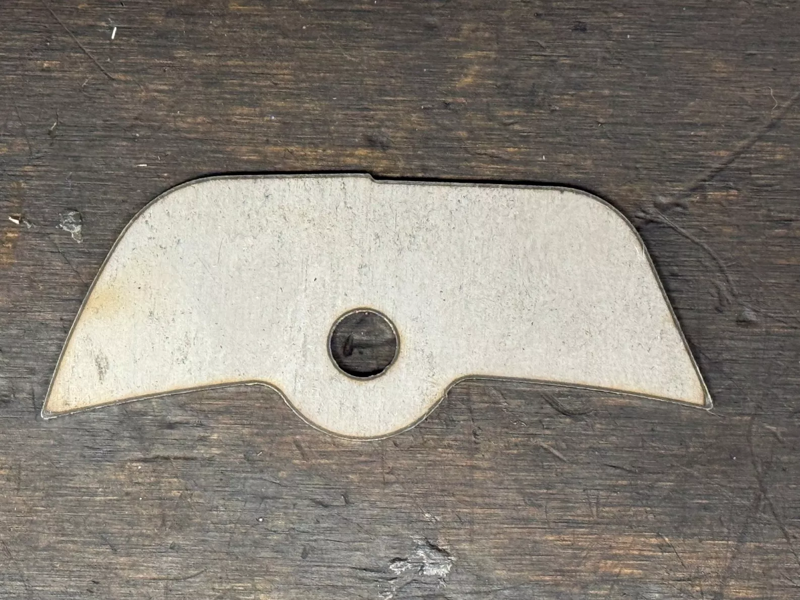
In this example, I’m using the Sketch Picture tool to create a 3D model of a shock mount for my Jeep that I can then 3D print to test subtle variations for improved clearance. I simply measured its width and emailed myself a photo from my phone.
Taking the Picture
It’s best practice to hold your phone (or digital camera) directly above the object being photographed to achieve a view that is normal to its surface. Holding the camera farther away achieves a more useful (2D) perspective, so feel free to use zoom. This also helps with lighting, as you’re less likely to cast a shadow on the object.
Speaking of lighting. It helps to place the object on something that'll provide color contrast. I chose a wooden workbench mostly for convenience, but found its dark color helped the steel stand out and the shadows disappear.
Once you snap the photo, email yourself the .jpeg.
Inserting the Picture
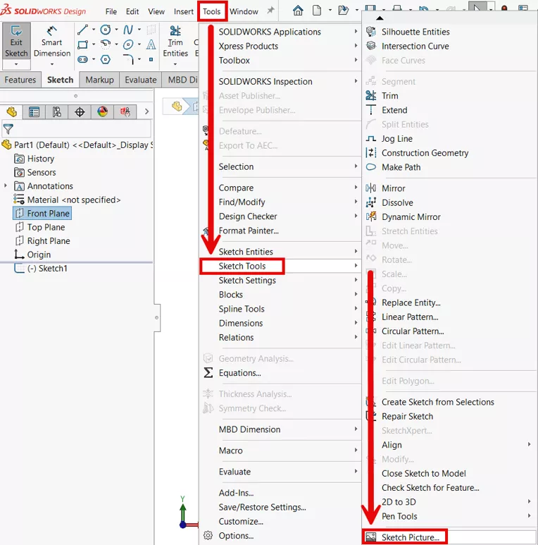
First, create a new sketch on a plane. Once inside the sketch, click on Tools > Sketch Tools > Sketch Picture.
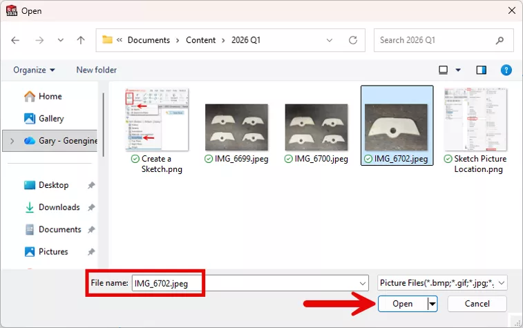
This will open a dialog box to select the image you need. Click the image and then click Open.
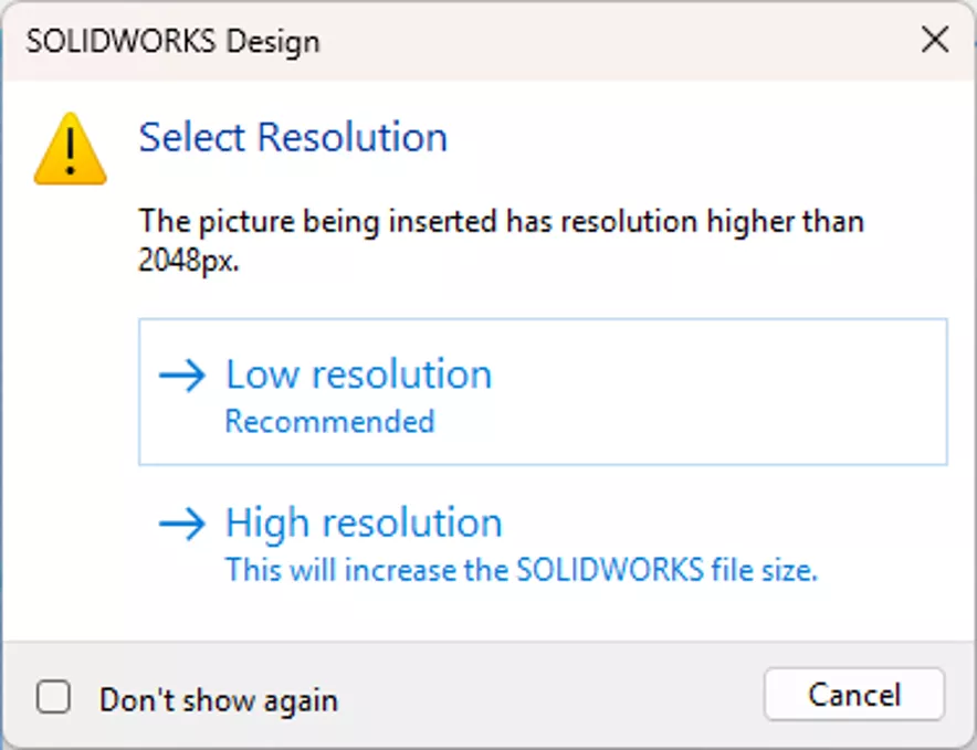
You might be prompted to select a resolution. Low resolution is usually fine (and will load faster).
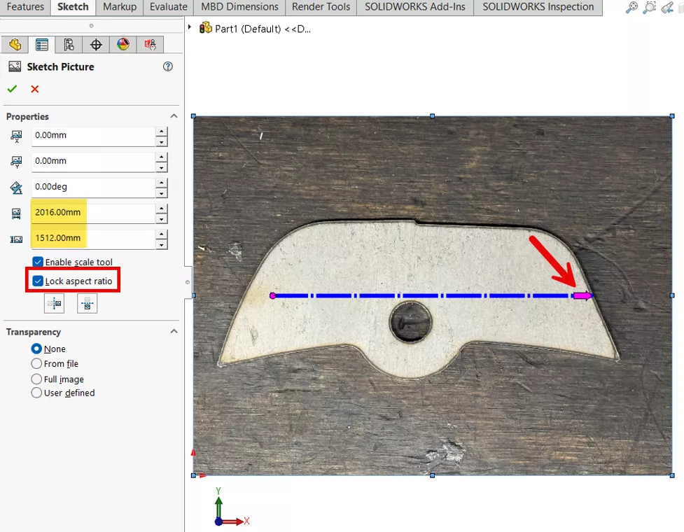
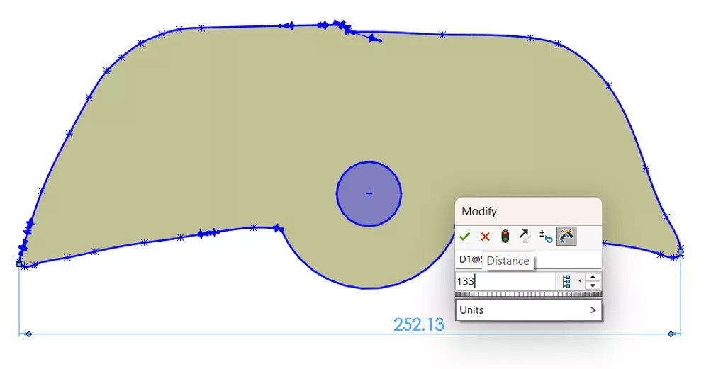
The image is then placed in the graphics area, where you can resize it (by dragging the arrow in the graphics area or manually entering dimensions in the PropertyManager on the left). Leaving the aspect ratio locked is key for creating an accurate part. I know that my part is 133mm wide, so I selected 200mm to get it in the right ballpark. For a photo from your phone, you can generally ignore the transparency section.
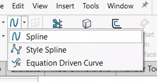
Sketching an Outline of the Image Using Splines
While tools like Autotrace can automatically create a sketched outline of an image, using splines to manually sketch along its edges will generally create a more accurate profile and let you differentiate between shadows and corners, something that Autotrace won’t always excel at.
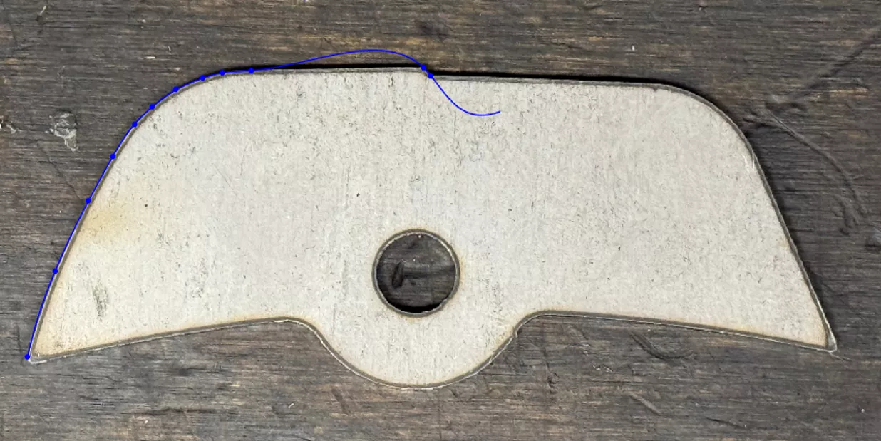
To start, I created a new sketch and began placing spline points along the edges. In areas with high curvature, I placed extra points to achieve greater control over the spline.
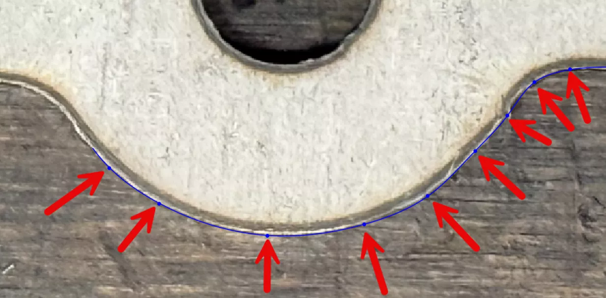
I added additional spline points and dragged the spline handles as needed to follow the contours of the part.
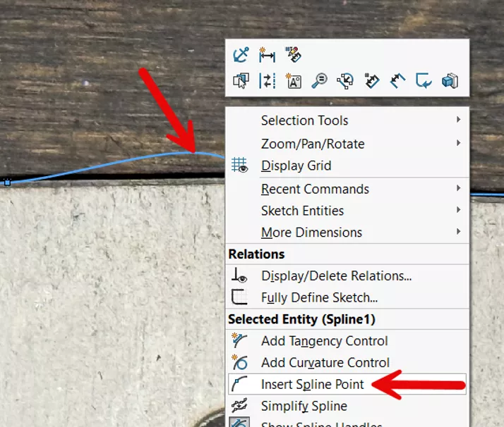
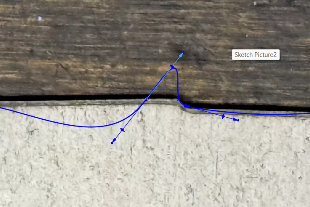
The finished sketch closely follows the contours of the part.
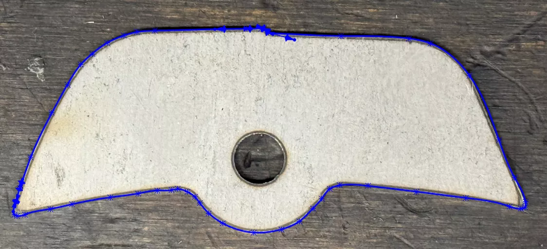
Making Changes to Customize the Part
An advantage of manually sketching the profile is that we can make subtle changes as needed. Because I intend to modify the part slightly, I made changes to the location of a few features.
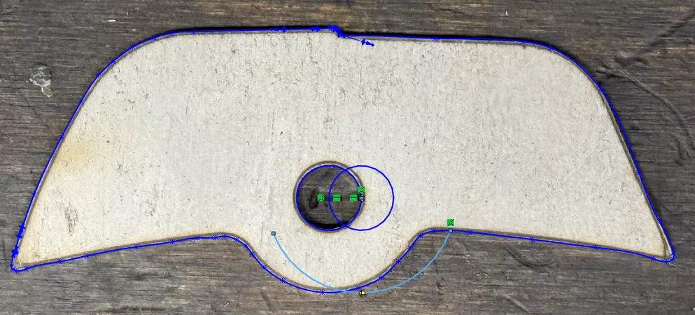
I added circular sketches instead of using only splines, and then added additional splines to connect them. I then used the Trim tool to remove unwanted splines. By hiding the original image in the feature tree, I now see only the sketch.
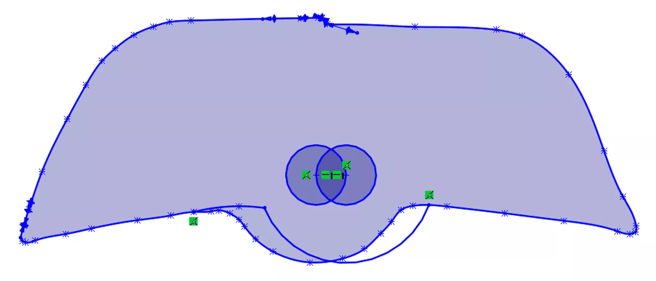
Creating the Extrude and Dimensioning for Accuracy
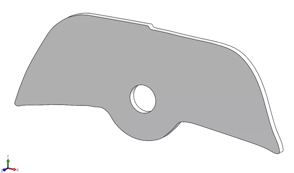
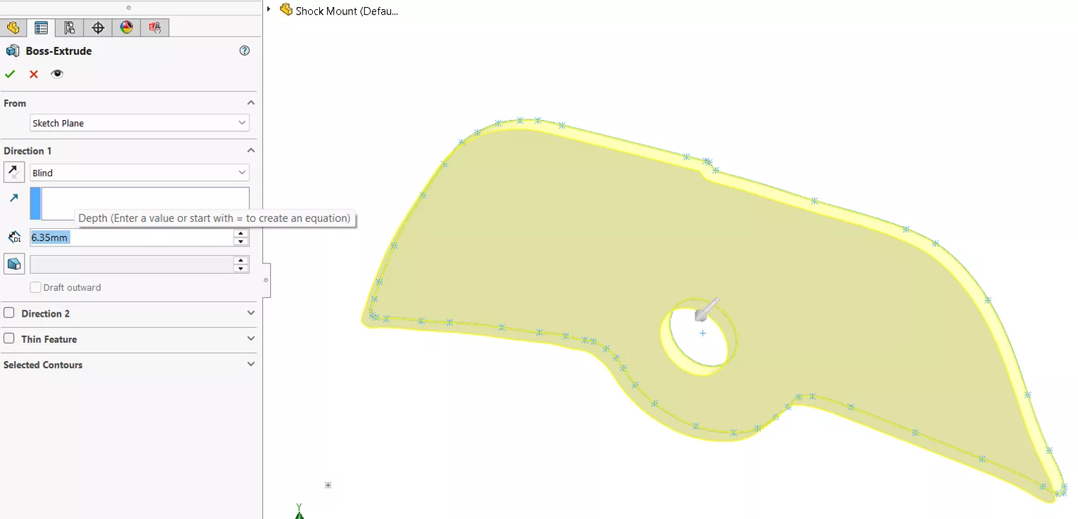
Once we have a closed contour, we can extrude the sketch to create a 3D part. I entered a thickness of 6.5mm, which roughly corresponds to the sheet metal thickness that I plan to use.
I then edited my sketch to add dimensions. Since nothing is dimensioned yet, I can change the size of the entire part by adding a single dimension. The other sketch dimensions scaled along with the width, giving me a part that matches the original in size.
I unhid the original photo with the extrusion visible to compare them. My part overlays the image perfectly and shows the changes I made to the shock tab to achieve better clearance between the spring bucket and the shock body.
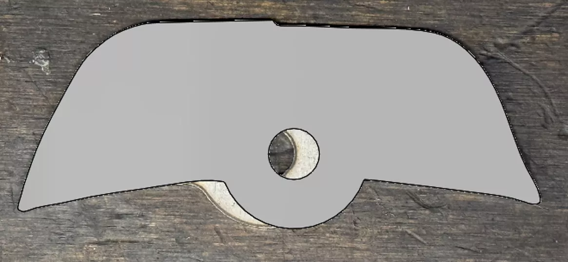
Now I’m ready to print my shock tabs so I can test them for clearance. The final tabs will be cut out of ¼” sheet metal, but some ABS is fine for the mock-up since the shocks won’t have any pressure in them.
One Final Tip
You can create a drawing of the part using a 1:1 scale and print it on paper, essentially turning the model back into a photo. If your plasma cutter is hand-held, you can then use the printout to trace the outline onto the metal.
SOLIDWORKS CAD Cheat Sheet
SHORTCUTS ⋅ MOUSE GESTURES ⋅ HOT KEYS
Our SOLIDWORKS CAD Cheat Sheet, featuring over 90 tips and tricks, will help speed up your process.
Want to learn more about SOLIDWORKS? Check out additional tutorials from our Technical team below. Additionally, join the GoEngineer Community, where you can create forum posts, enter design contests, and answer questions from other SOLIDWORKS users.
Related Articles
How to Create a Spring That Will Expand and Compress in a SOLIDWORKS Assembly
How to Make a Helix in SOLIDWORKS
Creating a Non-Circular Helix in SOLIDWORKS with Surfacing Commands
Replace a SOLIDWORKS Sketch Entity Without Rebuild Errors

About GoEngineer
GoEngineer delivers software, technology, and expertise that enable companies to unlock design innovation and deliver better products faster. With more than 40 years of experience and tens of thousands of customers in high tech, medical, machine design, energy and other industries, GoEngineer provides best-in-class design solutions from SOLIDWORKS CAD, Stratasys 3D printing, Creaform & Artec 3D scanning, CAMWorks, PLM, and more
Get our wide array of technical resources delivered right to your inbox.
Unsubscribe at any time.